
Gold Electrolysis Equipment

— Gold Electrolysis Equipment: High Current Density Cell to Au99.99 Ingots
Gold electrolysis equipment is an electrolytic refining cell that dissolves a cast crude-gold anode in a heated chlor-auric acid electrolyte and plates fine gold onto a seeded cathode, taking feed of 92% gold and above to Au99.99 ingots and, on a second electrolysis pass, to 99.999% gold. YuSai Machinery engineers the whole equipment package — anode casting and bagging, cell and electrode assemblies, AC-DC superimposed rectifier and titanium-clad copper busbar, electrolyte make-up, dosing, temperature and level control, closed fume hood with electrolyte condenser, PLC interlock panel, anode slime recovery and the melting and assay station — around your own anode assay, silver load and target daily output.Configuration: cell count, cathode area, rectifier rating, footprint, installed power and utilities are engineered to your anode assay, silver load and target daily output rather than taken from a catalogue of fixed models.
Product Overview
Gold electrolysis is an anodic refining process. A cast crude-gold anode is hung in a heated chloride electrolyte as the positive electrode of a direct-current circuit; the anode dissolves, gold enters solution as the tetrachloroaurate ion, and the same gold is reduced onto a seeded cathode as coherent metal while the silver and base metals alloyed with it stay in the electrolyte or report to an insoluble anode residue. Electrorefining, which is what this equipment does, dissolves a solid anode to purify metal that is already metallic, so the anode is both the feed and the electrochemical reactant. Electrowinning has no anode to dissolve and recovers metal that is already in solution, and cementation uses no current at all; a refinery typically needs all three, but they are three different machines. Gold’s position in the electromotive series is why the separation works: gold is more noble than hydrogen, silver and every base metal it is normally alloyed with, so it is the first species reduced as the cathode potential goes negative. That is also why the cell runs at 1–3 V — above that window the extra voltage is spent decomposing water and evolving gas rather than depositing gold, so a cell voltage that creeps upward at constant current is a symptom to be diagnosed, never a productivity setting to be raised.
The constraint that decides the commercial envelope is the anode, not the rectifier. Cathode current density can rise only as fast as circulation and agitation replenish the boundary layer against the cathode; beyond that the surplus current goes into water decomposition and the deposit turns dark, rough and poorly adherent. The limit specific to gold is silver. Silver oxidises at the anode face to silver chloride, which is essentially insoluble in this electrolyte: instead of dissolving away it builds a dense, poorly conducting film that blocks the dissolution reaction underneath it, drives the cell voltage up and finally passivates the plate, leaving a residual anode that still carries a significant fraction of the gold charged into it. Every practical gold cell is therefore designed around anode silver — the feed survey establishes the figure, the process design states the ceiling the cell can work within, inquartation and nitric parting are applied upstream where the anode is too silver-rich to run directly, and the rectifier carries a superimposed alternating component that breaks the film away continuously so dissolution continues until the plate is genuinely spent.
The electrolyte runs hot, in the 60–70 °C band, because both the conductivity of the chloride solution and the kinetics of gold deposition improve with temperature, and below that band the cell does not sustain the current density it was bought for. A hot chloride electrolyte also evaporates, and what evaporates carries gold: an open or partly open cell loses metal to the workshop atmosphere invisibly until the mass balance is closed. The equipment answer is the closed transparent hood coupled to a condenser, which returns that vapour to the cell rather than extracting and discarding it — holding metal loss below 0.02% of the gold charged — with automatic level dosing replacing the liquid that leaves with the fume. The last variable, and the one no equipment catalogue quotes, is the gold the process itself ties up: at 80 g/L, a 100-litre circuit holds roughly 8 kg of gold that is neither feedstock nor product, and YuSai sizes the electrolyte volume, circulation and bleed schedule as explicit design outputs. Anode purity, silver load and target output vary between plants, so the number of cells, cathode area, rectifier rating, electrolyte volume, heating and circulation duty, hood exhaust volume and condenser duty are all derived from your anode assay rather than taken from a fixed model list — a pilot running a few kilograms a day and a production refinery are the same engineering exercise at different scales.
Key Facts
- Final purity: Au ≥ 99.99% (Au99.99) as the standard product, delivered against a certificate of analysis; 99.999% is produced on a second electrolysis pass.
- Accepted anode: crude gold of 92% Au and above; 95% Au and above is the preferred operating band, because the anode dissolution reaction and the plate integrity both degrade as the base metal load rises.
- The binding constraint is silver, not gold. Silver in the anode oxidises to insoluble silver chloride, which coats the anode face as a dense film, raises the cell voltage and eventually stops dissolution altogether. The silver content of the anode is the first number that decides whether this route will work on your material.
- Cathode current density: up to 1,000 A/m² on the cathode, against the 200–800 A/m² band that conventional silver and gold electrolytic cells operate in.
- Electrolyte: chlor-auric acid in hydrochloric acid, held at 60–70 °C with gold at 80 g/L and above. That temperature is not optional — the electrolyte conductivity and the plating kinetics depend on it — and it is also why the cell has to be closed and condensed.
- Working inventory: the electrolyte itself carries gold. At 80 g/L, every 100 litres of electrolyte in the circuit is roughly 8 kg of gold held as solution, and that figure is designed down rather than left to grow.
- Loss control: the closed fume hood with a condenser returns vaporised electrolyte to the cell, holding metal loss below 0.02% of the gold charged.
- Configuration: cell count, cathode area, rectifier rating, footprint, installed power and utilities are engineered to your anode assay, silver load and target daily output rather than taken from a catalogue of fixed models.
Product Core Selling Points
- Silver is engineered as the primary constraint, not treated as a nuisance. Anode silver is measured in the feed survey, the tolerable ceiling is stated in the process design package, and the cell is specified around the equipment that holds the anode in dissolution when that ceiling is approached.
- A rectifier with a superimposed alternating component. Depositing on a pure direct current lets silver chloride build as an adherent film that blinds the anode; the superimposed alternation breaks that film away continuously, so the anode plate dissolves more completely and less gold is left in the scrap anode.
- High current density as a delivered figure. The cell is designed to run up to 1,000 A/m² on the cathode, which raises output per unit of cell volume — and the design answers the three costs that high current density normally brings: increased IR drop, silver chloride build-up and dendritic or nodular deposit growth.
- A closed cell that pays for itself in recovered metal. The cell runs at 60–70 °C, and at that temperature the electrolyte evaporates. The transparent closed hood coupled to a condenser returns that vapour instead of venting it, which is what keeps metal loss below 0.02% of the gold charged and keeps the workshop air free of acid mist.
- The gold held in solution is designed down, not ignored. Electrolyte volume, cell geometry, circulation and the bleed schedule are set so that the quantity of gold locked up as working inventory is known, stated and minimised — the single most under-discussed cost of electrolytic gold refining.
- Anode slime treated as a designed product stream. Silver chloride and platinum group metal residues are retained inside the anode bag rather than allowed to migrate to the cathode, collected on a defined schedule, and routed to the silver and PGM circuits as a declared intermediate.
- Electrolyte chemistry held inside a control loop. Gold concentration, free hydrochloric acid, temperature, level and circulation are held by the control system, with automatic level dosing that replaces the electrolyte carried out with the fume and a circulation loop that keeps the composition uniform through the cell.
- Cathode medium chosen from the product requirement. Titanium plate for a deposit that strips cleanly and carries no risk of seeding the product with a second metal, or a pure gold seed sheet where a titanium contact is unacceptable in the customer’s specification; the choice is recorded on the route sheet.
- Materials selected for hot chloride duty. Cell body and structural frame in polypropylene and PPH with an anti-ageing additive, busbars in titanium-clad copper, wetted parts in PP and PVDF, and a hood in transparent polymer so the electrodes can be watched without opening the cell.
- A PLC panel that intervenes rather than merely displays. Cell voltage, cell current and busbar temperature are monitored continuously, the rectifier is interlocked to stop on an abnormal reading, and every electrolysis parameter is logged and retained so that a batch deviation can be traced to the anode, the electrolyte or the power supply instead of being guessed at.
- The rectifier is physically separated from the cell atmosphere. It is enclosed in its own compartment, isolated from the acid vapour in the working area, which is what decides its service life in a gold refinery.
- Harvest, melting, sampling and assay are inside the scope. The customer receives a certificated ingot with a fire-assay determination and a retained sample, not a jar of cathode crystals and a purity claim.
- Configuration to the anode assay, with the numbers written down. Cell count, cathode area, rectifier rating, electrolyte volume, circulation rate, cooling or heating duty, hood exhaust volume and effluent load are engineered from your anode analysis and target daily output, and the resulting figures are stated in the process design package.
Application Scenarios
- Bullion refineries and mint-side refining departments. Operations that buy doré, scrap bullion, coin and mixed precious metal lots and need an in-house electrolytic step that produces a certified Au99.99 ingot instead of shipping a semi-refined bar for toll treatment.
- Gold mines producing doré on site. Mine bullion that has been smelted at the carbon elution or gravity circuit but sits below the purity required by the receiving refinery, upgraded where the silver and base metal load allows direct electrolysis.
- Jewellery manufacturers, casting houses and large workshops. Sprues, rejected castings, bench sweeps, polishing dust and old gold collected across a production year, consolidated and brought back to fine gold that can be re-alloyed to the workshop’s own specification.
- Precious metal traders and assay offices. Buyers of mixed karat scrap and second-hand bullion who need to establish the true fine-gold content of a lot and convert it to a standard, saleable form before it moves on.
- Electronics and printed circuit board recyclers. Facilities that already recover gold from connector, finger, CPU and plating strip liquors as a cemented powder or a sludge, and that want to convert that intermediate into a branded, assayed ingot rather than sell it at a discount to its contained gold.
- Copper, lead and nickel electrorefiners. Anode slime circuits where gold is concentrated with silver and the platinum group metals; once the slime leach has been reduced back to metallic gold, this is the cell that turns it into fine gold.
- Plating and surface finishing companies. Gold recovered from plating baths, strip liquors and rinse waters as a powder or a cemented precipitate, re-melted into an anode and refined back to plating-grade gold or to bullion.
- Secondary precious metal refineries running toll campaigns. Multi-customer operations that need a cell which can be drained, cleaned and re-charged quickly between campaigns, with electrolyte chemistry, cathode area and current programme all re-specifiable from one lot to the next.
- Pilot, laboratory and university metallurgy facilities. Small-batch installations used to establish the behaviour of a particular anode on a few kilograms before a production refinery is committed, and to train operators on the electrode handling and electrolyte discipline the process demands.
- Dental, laboratory and medical alloy processors. Dental alloy scrap, laboratory crucible residues and spent precious metal ware, after the base metal and silver content has been parted, refined to fine gold in house.
- Watch, eyewear and luxury goods makers. In-house gold recovery from manufacturing scrap and returned product, where the value is high, the lots are small and the material is frequently irreplaceable.
- Industrial operations with an in-house precious metal unit. Catalyst, electronics, chemical and glass manufacturers that accumulate gold-bearing residues and want the refining step inside their own compliance envelope instead of exporting the metal as waste.
- Precious metal accounting and vaulting operations. Businesses whose core requirement is a documented mass balance on a customer’s metal, where the per-batch parameter log and the retained sample are as important as the ingot itself.
- Operations driven by product specification rather than by scale. Buyers whose customer or exchange requires an ingot from a certified electrolytic route with a fire-assay certificate, and for whom the process route itself is part of the deliverable.
Applicable Raw Materials
Each feed below enters the cell at the point its composition requires. The determining number in every case is the silver content of the anode, because silver is what limits anode dissolution; the base metal load is the second consideration, and it is managed by pre-treatment and by the electrolyte bleed schedule. Feeds that arrive as a powder, a slime or a cemented precipitate are melted and cast into anodes before they reach the cell. Output is stated for each feed.
- Mine doré bars and smelted bullion. Bar and button doré from a carbon elution or gravity circuit smelt, containing gold with silver and a modest base metal load, cast or re-cast to anode geometry for direct electrolysis where the silver content sits inside the working ceiling. Output: Au ≥ 99.99% ingot; silver recovered from the anode slime.
- Crude gold anode plates cast from retorted or cemented gold. Cemented, retorted or ion-exchange-derived gold powder that has been melted, fluxed and cast into anode plates; the standard feed for a secondary refinery. Output: Au ≥ 99.99% ingot; slime to the silver and PGM circuits.
- Gold reduced from aqua regia or chloride solution. Powder produced by selective reduction from a chloride liquor, washed free of residual nitrate and chloride, dried and melted to an anode; the classic interface between a wet chemical refining line and the electrolytic cell. Output: Au ≥ 99.99% ingot; second-pass material to 99.999% where required.
- Karat jewellery scrap after inquartation and parting. 18K, 14K and 9K scrap and old gold that has been melted with silver or copper, granulated and parted in nitric acid so that the silver and base metals are removed before the gold is melted into anodes. Output: Au ≥ 99.99% ingot; silver nitrate solution to the silver circuit.
- Bench sweeps, polishing dust and workshop residues. Incinerated, milled, blended and sampled material from jewellery manufacture, smelted to an anode after the burn-off of organics and the removal of ferrous contamination. Output: Au ≥ 99.99% ingot; slag returned for re-milling.
- Gold-bearing anode slime after leaching and reduction. Gold recovered from copper, lead or nickel electrorefining slime, reduced back to metal, melted and cast; frequently the highest-value lot a secondary refinery handles. Output: Au ≥ 99.99% ingot; silver and PGM fractions separated upstream and downstream.
- Electronic scrap gold concentrate. Gold from fingers, connectors, CPU packages and plating strip liquors, recovered as a cemented powder or a sludge, refined and melted to an anode; the base metal load is usually the reason this material is electrolysed rather than sold as a concentrate. Output: Au ≥ 99.99% ingot; copper and nickel retained in the electrolyte and bled off.
- Deplated and stripped coating gold. Gold recovered from stripped watch cases, spectacles, connectors and decorative ware, collected as a foil or a powder and consolidated into an anode. Output: Au ≥ 99.99% ingot.
- Dental and laboratory alloy scrap. Dental casting alloys, laboratory crucibles, electrodes and precious metal ware, parted where necessary and cast to anodes. Output: Au ≥ 99.99% ingot; PGM content to the PGM circuit.
- Gold–silver and gold–PGM alloy scrap. Au–Ag alloy strip, Au–Pt and Au–Pd alloy scrap and brazing alloys, where the anode is high-grade in gold but carries a PGM load that reports to the anode slime rather than to the electrolyte. Output: Au ≥ 99.99% ingot; PGM concentrate from the anode slime.
- Recycled bullion, coin and bar material. Old bars, coins and bullion whose provenance requires re-refining before resale, run as anode plates cast directly from the melted material. Output: Au ≥ 99.99% ingot with a fresh certificate of analysis.
- Gold recovered by electrowinning or cementation. Cathode sludge and cemented precipitate from solution-side recovery circuits, dried and melted to anodes; this is the standard route by which gold recovered from a liquor is brought up to bullion standard. Output: Au ≥ 99.99% ingot.
- Consigned and toll-refining lots. Customer-owned gold run as a discrete campaign with its own mass balance, parameter log and retained sample, consolidated into anodes and refined on a per-lot basis. Output: Au ≥ 99.99% ingot with a lot-specific mass balance and certificate.
- Second-pass electrolysis feed. Material that has already passed through a first electrolytic cycle and is charged again to reach 99.999%, either as an anode cast from first-pass cathode gold or as crystal returned to the cell. Output: 99.999% gold ingot.
Finished Products
The cell is configured around the product form the customer sells, holds or re-uses, from cathode gold crystal through to a certificated ingot. Where the customer already operates a melting and assay shop, the line is delivered with the cell, harvesting and drying stages only; where it does not, the melting, casting and assay equipment are included.
- Fine gold ingot and button. The primary output, poured from cathode gold and assaying 99.99% and above, conforming to the Au99.99 Grade 1 specification of the Shanghai Gold Exchange and produced against a fire-assay determination with a cross-check on the certificate of analysis. Output: certificated fine gold ingot or button.
- 99.999% gold. Produced by charging first-pass gold as the anode of a second electrolysis cycle, for buyers whose specification, customer or end use calls for the higher standard. Output: 99.999% gold ingot with a separate certificate of analysis.
- Cathode gold crystal and deposits. The as-deposited product harvested from the cathode before melting, supplied where the customer prefers to handle, sample or re-melt the metal in its own furnace. Output: washed cathode gold crystal at declared purity.
- Anode slime — silver chloride fraction. The silver carried in the anode, rejected at the anode face as silver chloride and retained inside the anode bag, supplied as a washed and dried intermediate to the silver refining circuit or to a customer who refines silver in house. Output: AgCl-rich slime at declared silver content.
- Anode slime — platinum group metal fraction. Platinum, palladium, rhodium and iridium carried in the anode and rejected into the slime, supplied as a dried high-grade concentrate declared by metal content. Output: PGM-bearing anode slime routed to the PGM refining line.
- Spent anode scrap and hanger residues. Residual anode plate that has reached the end of its dissolution cycle, returned to the melting furnace and cast into fresh anodes rather than sold. Output: remelted anode stock returned to the circuit.
- Electrolyte bleed solution. Electrolyte withdrawn on the defined bleed schedule to keep the silver and base metal concentration inside the working window, containing gold that is recovered before the bleed leaves the plant. Output: gold recovered from the bleed; silver and base metal solution to the silver circuit.
- Rebuilt electrolyte returned to the cell. Fresh chlor-auric acid made up and returned to the circuit after gold recovery from the bleed, holding the working gold concentration inside the control band. Output: electrolyte at 80 g/L gold and above, returned to service.
- Recovered fume condensate. Electrolyte condensed from the cell headspace and returned to the cell rather than vented, which is the mechanism behind the sub-0.02% metal loss figure. Output: electrolyte returned to the cell; acid mist removed from the working atmosphere.
- Gold-bearing filter media and residues. Filter cartridges, bag cloth, gaskets and container rinses from the electrolyte circuit, processed rather than discarded so that entrained gold leaves the plant as metal and not as waste. Output: recovered gold returned to the melting station.
- Certificate of analysis, mass balance and retained sample. Every lot is released with the anode assay, the electrolyte assay, the slime assay and the product assay, the parameter log for the electrolysis cycle, and a retained reference sample held for the warranty period. Output: batch record and certificate of analysis.
Gold Electrolysis Equipment Process Flow
The nine stages below form the standard gold electrolysis equipment sequence, from the assay that decides whether the anode can be run directly through to a certificated ingot and a rebuilt electrolyte. Step 1 and Step 6 are the two stages that decide whether the route works at all: the anode silver figure established at Step 1 sets the whole design, and the silver chloride control applied at Step 6 is what keeps the anode dissolving once the cell is running. Engineering setpoints — current density, cell voltage, electrolyte gold concentration, free acid, temperature, circulation rate, bleed schedule and anode loading — are fixed during process design against your own anode assay.

Gold electrolysis equipment process flow — from crude gold anode to a certificated Au99.99 ingot, with silver chloride passivation control and electrolyte condensation inside the same cell.
Steps 1 — Feed Assay and Anode Plate Casting. The lot is weighed, sampled by riffling and splitting, and assayed before anything is charged. Gold is determined by fire assay with an ICP-OES cross-check, silver by titration or ICP-OES, and the base metal and platinum group metal inventory by ICP-OES; the anode silver figure is the number that governs the rest of the design, and the PGM figure determines how much value will report to the anode slime. Material that is already metallic is melted under flux and cast into anode plates of controlled thickness and geometry, with the plate dimensions, hanger positions and cast weight recorded against the lot number. Material that is too silver-rich to run directly is routed to inquartation and nitric parting first, which removes the silver before the anode is cast; material that arrives as a powder, a slime or a cemented precipitate is dried, fluxed and consolidated into a cast anode rather than fed loose. The assay output fixes the anode loading, the target current and the bleed schedule for the campaign. Reagent and utility input: riffling and sample splitting equipment, fire assay apparatus and ICP-OES, melting furnace with flux and mould set, anode casting and cooling station, hanger preparation. Output: anode plates at a recorded weight and assay; route sheet and lot record.
Steps 2 — Anode Bagging and Cathode Seeding. The anode is wrapped in a bag or fitted with a membrane before it goes anywhere near the cell, and this is not a finishing detail but a functional stage. Silver chloride and any platinum group metal residue are insoluble, and if they are free to move they will migrate to the cathode and report to the product as contamination; the bag holds them at the anode and keeps the cathode deposit clean. The anode is fitted to its hanger, the contact faces are cleaned and dressed, and the assembly is checked for straightness, because a bowed or badly hung anode changes the inter-electrode distance along its length and produces an uneven current distribution that shows up later as a localised burn. On the cathode side, titanium plate is prepared by degreasing and passivation, or a pure gold seed sheet is fitted, checked for flatness and cleaned. Busbar contact faces are cleaned on both sides and the electrode spacing is set with a gauge, because a resistive contact on a single cathode is notoriously difficult to diagnose once the cell is closed and filled. Reagent and utility input: anode bag or membrane material, anode hangers and hooks, cathode plates or seed sheets, degreasing and passivation agents, spacing gauges, busbar cleaning and contact dressing. Output: bagged anode assemblies; prepared cathode assemblies with verified contact and spacing.
Steps 3 — Chlor-Auric Electrolyte Make-Up. The electrolyte is a chlor-auric acid solution in hydrochloric acid, and how it is made up determines how the cell behaves for the whole campaign. Gold is brought into solution as the tetrachloroaurate ion and is held at a working concentration of 80 g/L and above, with free hydrochloric acid maintained in the 10–12% band to keep the solution conducting and to keep the gold complex stable; the exact figures for your cell are fixed in process design against the anode assay and the expected silver load. Make-up is carried out in the electrolyte preparation vessel with agitation, metered acid addition and fume extraction, and the liquor is brought to the working temperature band before it is transferred. Gold and free acid are analysed on the made-up electrolyte, and the result is recorded against the batch, because the single most common cause of a disappointing first campaign is an electrolyte that was never assayed. Reagent and utility input: chlor-auric acid solution, hydrochloric acid with metered dosing, electrolyte preparation vessel with agitation and extraction, heating, circulation pump, gold and free acid analysis. Output: electrolyte at 80 g/L gold and above with free acid in the working band; electrolyte make-up record.
Steps 4 — Rectifier Set-Up and AC-DC Superposition. This is the stage that distinguishes a gold electrolysis rectifier from a general-purpose plating supply. The rectifier is set to the current and voltage programme fixed in process design, and an alternating component is superimposed on the direct current. The superimposed alternation reverses the current for part of every cycle, which periodically strips the freshly formed silver chloride film off the anode face so that it cannot build into a continuous passivating layer; with a pure direct current that film becomes adherent, blocks dissolution underneath it and leaves a residual anode carrying unrecovered gold. The cathode is also started on a ramp rather than at full current: a modest initial current produces a coherent, fine-grained seed deposit that stays coherent as it thickens, whereas a cold start at full current produces a burst of nodules and a deposit that sheds back into the electrolyte. Individual cathode currents are verified after start-up, cell voltage is checked against the design figure, and busbar temperature is confirmed to be stable. Reagent and utility input: rectifier with adjustable voltage and current, AC-DC superposition unit with adjustable alternating component, staged current programme, individual cathode current check, busbar temperature monitoring. Output: stable current distribution across the cathode set; coherent seed deposit established; silver chloride film held in check from the first hour.
Steps 5 — High Current Density Gold Deposition. This is the stage that sets the plant output. The cell runs with a cathode current density up to 1,000 A/m², which is the high-current-density regime against the 200–800 A/m² band that conventional electrolytic gold and silver cells occupy, and the cell is designed for it rather than merely rated for it. High current density is paid for in three currencies: IR drop across the electrolyte gap, which rises with current and with the silver and base metal concentration in the liquor; silver chloride build-up at the anode, which is why the superimposed alternating component and the anode bag are not optional at this current; and deposit morphology, because a deposit grown too fast at a starved boundary layer turns nodular and dendritic and can bridge the gap to the anode. Boundary layer control is therefore part of the deposition stage: circulation keeps the gold concentration at the cathode face close to the bulk concentration, agitation is set to the design rate, and the temperature is held in the 60–70 °C band, which both lowers the electrolyte resistance and improves the plating kinetics. Anode loading and cathode area are matched so that the cell does not run out of dissolved gold before the deposit reaches its design load. Reagent and utility input: rectifier at design current, circulation pump, agitation, temperature control loop with heating, gold and free acid monitoring, cell voltage and current logging. Output: gold deposition at up to 1,000 A/m² cathode current density; gold tenor in the cell falling towards the depletion target; a coherent cathode deposit.
Steps 6 — Silver Chloride Film Management. Silver is the specific problem this equipment is built around, and this stage is where it is managed. As the anode dissolves, the silver alloyed with the gold is oxidised and immediately precipitates as silver chloride, which is essentially insoluble in the chloride electrolyte. Left alone, that chloride builds a dense, poorly conducting layer on the anode face, the effective anode area falls, the local current density on the remaining exposed metal rises, the cell voltage climbs, and the anode finally passivates with a substantial fraction of its gold still undissolved. Four measures run together at this stage. The anode silver content is held inside the working ceiling by upstream parting where the feed requires it. The superimposed alternating current established at Step 4 continues to shed the film mechanically and electrochemically. The anode bag retains the detached chloride so it cannot reach the cathode. And the operator monitors the anode for visible film build-up, lifting and inspecting the plate on the schedule set in the process design, brushing or knocking the chloride loose where it has accumulated and returning the anode to the cell. The electrolyte is also sampled through this stage, because silver that has gone into solution rather than into the bag raises the silver concentration in the working liquor and eventually forces a bleed earlier than scheduled. Reagent and utility input: superimposed alternating current from the rectifier, anode bagging and membrane materials, anode inspection and cleaning tooling, sampling of anode face and electrolyte, silver analysis. Output: an anode that dissolves to completion rather than passivating; silver chloride retained in the bag as a recoverable fraction; silver concentration in the electrolyte tracked against the bleed threshold.
Steps 7 — Cell Voltage and Busbar Supervision. Cell voltage is read as a diagnostic rather than used as a control handle, and the readings taken at this stage are what keep a fault from running to the end of the campaign. The cell runs inside the 1–3 V working window, and the reason the window exists is that gold deposition is the favoured reaction only inside it; voltage applied above the window is consumed by water decomposition and gas evolution instead of by gold deposition, and it drives the deposit towards roughness and poor adhesion at the same time. A cell voltage that rises at constant current is therefore diagnosed in a fixed order: busbar and hanger contact resistance first, then inter-electrode spacing and anode geometry, then electrolyte conductivity and free acid, then temperature, then the condition of the anode face. Current and voltage on each electrode pair, busbar temperature and electrolyte temperature are all logged continuously, and the rectifier is interlocked to stop on an abnormal reading rather than allowed to continue. Correcting a dark, poorly adherent or blackened cathode is done by reducing the voltage, not by raising it — high voltage over-oxidises the deposit, which then sheds back into the solution and costs both grade and recovery. Reagent and utility input: cell voltage, cell current and busbar temperature monitoring, per-electrode current check, contact cleaning and re-dressing, electrolyte sampling, PLC interlock and alarm log. Output: a fault identified and corrected within the cycle; corrected settings recorded against the batch; deposit grade held to specification.
Steps 8 — Cathode Harvest and Ingot Casting. When the cathode has taken up its design load — judged from the ampere-hours passed against the deposit weight and confirmed by weighing the drained cathode — the cell is taken out of service and the cathode is lifted. The deposit is washed to remove adhering electrolyte, because electrolyte left on the crystal carries gold back out of the circuit in the wash water and contaminates the melt with chloride and silver; the wash water is collected and returned rather than sewered. The drained, weighed cathode gold is then dried and melted under flux with the flux formulation matched to the deposit, and the melt is sampled and cast to the product form the customer requires — ingot, button or granule. The ingot is analysed by fire assay with an ICP-OES cross-check, and the batch is released only when the analysis confirms the specified grade. Reagent and utility input: cathode lifting and handling frame, washing station with collected wash water, drying oven, melting furnace with flux and mould set, sampling and fire assay, ICP-OES cross-check, ingot marking equipment. Output: certificated Au ≥ 99.99% ingot or button; wash water returned to the circuit; batch record with the product assay.
Steps 9 — Anode Slime and Electrolyte Rebuild. The campaigns are closed here, and the two streams that carry residual value are recovered rather than written off. The anode bag is opened and the silver chloride slime is washed free of entrained electrolyte, dried, weighed and assayed for silver; where the anode carried platinum group metals, the PGM fraction in the slime is separated and declared by metal content before it leaves for the PGM refining line. Residual anode plate that reached the end of its dissolution cycle is returned to the melting station and cast into fresh anodes instead of being sold as scrap. The electrolyte is analysed for gold, free acid, silver and base metals, and bled on the schedule set in process design; gold is recovered from the bleed before the liquor leaves the plant, and the rebuilt electrolyte is returned to the cell at the working concentration. The cell, hood, condenser, ducting and filter media are cleaned on the same schedule, and the condensate recovered from the fume is returned to the cell. Every filtrate, wash water and rinse is assayed, and the mass balance for the lot — anode in, ingot out, slime out, electrolyte in circuit, losses accounted for — is closed and issued with the batch record. Reagent and utility input: anode bag opening and slime washing station, vacuum or pressure filtration, drying oven, slime and electrolyte assay, bleed and gold recovery from the bleed, electrolyte rebuild, cell and condenser cleaning, mass balance reconciliation. Output: washed and assayed anode slime with the silver and PGM fractions declared; rebuilt electrolyte returned to the cell; residual anode stock remelted; closed mass balance and certificate of analysis.
Product Structure (Main Equipment)
The equipment package is assembled from the six groups below. Materials of construction are selected for hot chloride duty and for the small quantity of electrolyte that inevitably escapes the circuit: cell bodies and structural frames in polypropylene and PPH with an anti-ageing additive, busbars in titanium-clad copper, anode bags in acid-resistant woven polymer, wetted piping and ducting in PP and PVDF, and a hood in transparent polymer so that the electrodes and the anode face can be observed without opening the cell.
Anode preparation, casting and handling
- Gold melting and anode casting furnace. Induction or resistance furnace with a matched crucible, flux formulation and anode mould set, used to melt consigned gold, cathode gold, cemented powder, slime-derived gold and residual anode scrap into anode plates of controlled thickness, geometry and weight. Output: cast anode plates with recorded weight and assay.
- Anode mould set and cooling station. Moulds sized to the anode envelope the cell accepts, with a controlled cooling station so that the plates are cast without shrinkage voids and are straight enough to hang at a uniform distance from the cathode. Output: dimensionally consistent anode plates.
- Anode hangers, hooks and contact bars. Titanium-clad copper hangers that carry the anode at the design immersion depth, with contact faces machined to sit flat on the busbar; the hanger is the anode’s only electrical connection and its condition is the first suspect when a cell voltage rises. Output: mounted anode assemblies at a verified immersion depth.
- Anode bags and membrane frames. Acid-resistant bag or membrane assemblies fitted around each anode to retain the insoluble silver chloride and PGM residue at the anode face and keep it out of the cathode deposit. Output: contained anode residue with the cathode deposit protected.
- Anode inspection and cleaning tooling. Lifting frame, inspection station and non-metallic scraping and brushing tools used to inspect the anode face and dislodge accumulated chloride on the schedule set in process design. Output: inspected and cleaned anode returned to service.
- Anode scrap return and remelt station. Collection and handling for residual anode plate, hanger residues and cell-bottom material, all of which are returned to the melting station rather than sold. Output: remelt stock returned to anode casting.
Electrolytic cell and electrode assemblies
- Electrolytic cell body. Integrally formed polypropylene or PPH tank with an anti-ageing additive, sized to the anode and cathode set and to the electrolyte volume the design allows, with welded rib reinforcement and a sealed base so the cell can stand over a containment tray without leaking. Output: the primary process vessel.
- Cell lid and transparent closed hood. Sealed lid and transparent polymer hood that enclose the cell headspace, allow the electrodes, the anode face and the electrolyte to be watched during the run without opening the cell, and duct the vapour to the condenser under negative pressure. Output: an enclosed cell with visual access and controlled vapour containment.
- Cathode assemblies. Titanium plates selected for clean stripping and freedom from second-metal contamination, or pure gold seed sheets where the customer’s specification rules out a titanium contact; supplied as a matched set with hanger bars and insulated supports. Output: the deposition surface and the deposit carrier.
- Cathode position and spacing system. Insulated retaining comb or spacer system that holds every cathode at the design inter-electrode distance from its anode along the full immersed length, which is what keeps the current distribution even and prevents a localised burn. Output: uniform electrode spacing and even current distribution.
- Busbar set and contacts. Titanium-clad copper busbars with compression clamps, insulated supports and machined contact faces, sized to carry the full cell current with minimal voltage drop across the cell. Output: even current distribution and a measurable base for fault detection.
- Electrode lifting and setting frame. Lifting frame for cathodes, anodes and cell lids, designed so that routine inspection and harvesting do not depend on improvisation and the electrodes are never dragged across the cell edge. Output: safe and repeatable electrode handling.
- Containment tray and cell floor. Acid-resistant tray under the cell that contains any electrolyte spill and holds it for recovery rather than letting it reach the floor drain. Output: spill containment with recoverable liquor.
Electrolyte preparation and circulation
- Electrolyte preparation vessel. Agitated vessel with metered acid dosing and fume extraction in which chlor-auric acid electrolyte is made up to the working gold concentration and free acid band. Output: electrolyte made up to specification with a recorded make-up analysis.
- Electrolyte circulation pump. Acid-resistant pump with PP or PVDF wetted parts that keeps the electrolyte moving through the cell, refreshing the boundary layer at the cathode face and preventing stratification of the denser gold-rich liquor at the bottom of the tank. Output: uniform electrolyte composition and a sustained mass-transfer rate.
- Temperature control loop. Heating and, where the duty requires it, cooling system with a temperature probe and controller that holds the electrolyte in the 60–70 °C working band; the band is fixed by the chemistry, and both the conductivity and the plating kinetics depend on it. Output: electrolyte held in the working temperature band.
- Automatic level dosing system. Level sensing with metered make-up addition that replaces the electrolyte carried out with the fume, so the cell does not run down in level and the working concentration is held rather than drifting between shifts. Output: electrolyte level and concentration held inside the control band.
- Gold and free acid monitoring. Sampling and analysis regime with the glassware and instrumentation needed to determine gold, free hydrochloric acid, silver and base metals in the working electrolyte, so the bleed decision is taken on measurement rather than on appearance. Output: electrolyte assay trend used to set the bleed schedule.
- Electrolyte filtration. Cartridge or bag filtration ahead of the cell that removes suspended solids which would otherwise blind the anode bag, plate onto the cathode and contaminate the deposit. Output: particle-free electrolyte.
- Bleed tank and gold recovery from the bleed. Tank that receives electrolyte withdrawn on the bleed schedule and the equipment that recovers the gold from it before the liquor leaves for the silver circuit. Output: gold returned to the melting station; silver-bearing bleed to the silver circuit.
Power supply, control and instrumentation
- Electrolytic rectifier. Adjustable, current-limited DC supply with a voltage range that covers the working window and the headroom the start-up ramp requires, sized to the cell current the cathode area and electrolyte support. Output: controlled direct current to the cell.
- AC-DC superposition unit. Superimposed alternating current module with an adjustable alternating component, fitted to break the silver chloride film away from the anode face continuously so that the plate dissolves to completion instead of passivating. Output: sustained anode dissolution on silver-bearing anodes.
- PLC control and operator interface. Touch-screen panel controlling the rectifier, circulation, heating and dosing, running a staged automatic cycle in which each stage carries its own voltage and duration, with a manual mode for intervention. Output: repeatable automatic cycles and reproducible batches.
- Voltage, current and busbar temperature monitoring. Continuous measurement of cell voltage, cell current and busbar temperature with interlocks that stop the rectifier on an abnormal reading instead of allowing a fault to run to harvest. Output: faults detected before they become unrecovered metal.
- Parameter logging and batch history. Storage and retrieval of the electrical and process record for every campaign, so a deviation can be traced to the anode, the electrolyte or the power supply rather than guessed at. Output: per-batch process record filed with the assay results.
- Enclosed, isolated rectifier compartment. The rectifier is physically separated from the cell atmosphere so that acid vapour does not attack its internals, which is what decides its service life in a gold refinery. Output: extended power supply service life.
Fume containment, condensation and abatement
- Electrolytic rectifier. Adjustable, current-limited DC supply with a voltage range that covers the working window and the headroom the start-up ramp requires, sized to the cell current the cathode area and electrolyte support. Output: controlled direct current to the cell.
- AC-DC superposition unit. Superimposed alternating current module with an adjustable alternating component, fitted to break the silver chloride film away from the anode face continuously so that the plate dissolves to completion instead of passivating. Output: sustained anode dissolution on silver-bearing anodes.
- PLC control and operator interface. Touch-screen panel controlling the rectifier, circulation, heating and dosing, running a staged automatic cycle in which each stage carries its own voltage and duration, with a manual mode for intervention. Output: repeatable automatic cycles and reproducible batches.
- Voltage, current and busbar temperature monitoring. Continuous measurement of cell voltage, cell current and busbar temperature with interlocks that stop the rectifier on an abnormal reading instead of allowing a fault to run to harvest. Output: faults detected before they become unrecovered metal.
- Parameter logging and batch history. Storage and retrieval of the electrical and process record for every campaign, so a deviation can be traced to the anode, the electrolyte or the power supply rather than guessed at. Output: per-batch process record filed with the assay results.
- Enclosed, isolated rectifier compartment. The rectifier is physically separated from the cell atmosphere so that acid vapour does not attack its internals, which is what decides its service life in a gold refinery. Output: extended power supply service life.
Harvesting, melting and assay
- Cathode washing station. Washing station with collected wash water in which the harvested cathode is rinsed free of adhering electrolyte before drying, so that gold is not carried out of the circuit on the crystal and chloride and silver do not enter the melt. Output: washed cathode gold and wash water returned to the circuit.
- Drying oven. Controlled-temperature oven that dries the cathode gold, the anode slime and the filter cake ahead of melting and assaying. Output: dry material ready for melting or assay.
- Melting furnace, flux and mould set for the product. Induction or resistance furnace with a flux formulation matched to the deposit and a mould set for the product form required, whether that is an ingot, a button or granules. Output: cast precious metal product.
- Sampling and assay station. Fire assay apparatus, ICP-OES, sample preparation and a dedicated fume hood, so that the anode, electrolyte, slime and product assays for a campaign are produced in house on the day the campaign closes. Output: certificate of analysis issued against the batch.
- Slime washing, filtration and drying train. Vacuum or pressure filtration with a drying oven for the anode bag contents, so the silver and PGM fraction can be washed, dried, weighed and declared by metal content. Output: washed and assayed anode slime declared by metal content.
- Retained sample store. Sealed sample store holding the feed, intermediate and product samples for each lot for the warranty period. Output: retained reference sample per lot.
Product Features
- Anode-first specification. The anode assay, and the silver figure inside it, is the input that fixes the cell current, the cathode area, the electrolyte volume, the bleed schedule and the pre-treatment requirement, so the equipment is specified against the material rather than against a nominal capacity.
- AC-DC superimposed rectifier as standard. The alternating component that keeps silver chloride from passivating the anode is built into the power supply rather than offered as an option, because on silver-bearing gold anodes it is the difference between a plate that dissolves and a plate that has to be remelted.
- High current density engineered, not claimed. The cell is designed to run to 1,000 A/m² on the cathode, with the circulation, agitation, temperature control, electrode spacing and anode loading that the current density requires, rather than a rating applied to a cell that cannot sustain it.
- Silver chloride retained where it forms. Anode bagging and membrane frames hold the insoluble silver and PGM residue at the anode so it cannot migrate to the cathode, which protects the deposit grade and turns the residue into a recoverable, assayable stream.
- Closed, transparent cell with an electrolyte condenser. The hood encloses the headspace, the condenser returns vaporised electrolyte, and the transparent panel keeps the anode face and the deposit visible so that film build-up and deposit quality can be seen without breaking containment.
- Metal loss below 0.02% of the gold charged. The figure is a consequence of the closed hood and the condenser, not an aspiration: at 60–70 °C the electrolyte evaporates, and the condenser is what stops that vapour from carrying gold out of the plant.
- Automatic level dosing matched to the fume rate. The electrolyte that leaves with the vapour is replaced on a control loop, so the cell neither runs down in level nor drifts in concentration between shifts.
- Working gold inventory treated as a design output. Electrolyte volume and cell geometry are set to keep the gold held as solution at a known and stated figure, and the bleed recovery is part of the plant scope rather than a downstream service.
- Electrolyte chemistry under measurement, not judgement. Gold, free acid, silver and base metals are determined on the working liquor, and the bleed is taken on the schedule those results dictate rather than when the cell starts to behave badly.
- Cell voltage read as a diagnostic. The 1–3 V working window is enforced, per-electrode current is checkable, and a rising cell voltage is worked through a fixed diagnostic order — contact, spacing, conductivity, temperature, anode condition — instead of being answered with more voltage.
- Voltage discipline written into the procedure. A dark, poorly adherent or blackened cathode is corrected by reducing the voltage, and that correction is part of the operating procedure rather than left to operator judgement.
- Interlocked PLC with per-batch history. Voltage, current and busbar temperature are monitored continuously, the rectifier stops on an abnormal reading, and the electrical and process record for every campaign is retained with the assay results.
- Rectifier isolated from the cell atmosphere. The power supply sits in its own enclosed compartment clear of the acid vapour in the working area, which is the single largest determinant of its service life.
- Materials chosen for hot chloride duty. Polypropylene and PPH with an anti-ageing additive for the cell and frame, titanium-clad copper for the busbars, acid-resistant polymer for the bags and membranes, and PP and PVDF for the wetted piping and ducting.
- Cathode medium selected from the product requirement. Titanium plate for clean stripping or a pure gold seed sheet where a titanium contact is unacceptable, with the choice recorded on the route sheet rather than left to stock on hand.
- Anode residual returned, not sold. Residual plates, hanger residues and cell-bottom material go back to the melting station and into fresh anodes, which is how the anode-side gold balance is closed.
- Slime and bleed both declared by assay. The silver chloride fraction and the PGM fraction leave as washed, weighed and assayed intermediates, and the electrolyte bleed is recovered for its gold before it goes to the silver circuit.
- Melting, sampling and assay inside the scope. The customer receives a certificated ingot with a fire-assay determination, an ICP-OES cross-check and a retained sample, not a jar of crystal and a purity claim.
- Closed mass balance per lot. Anode in, ingot out, slime out, electrolyte in circuit and losses accounted for, issued with the batch record — which is what makes a recovery guarantee checkable rather than rhetorical.
- Configuration to the assay, not to a catalogue. Cell count, cathode area, rectifier rating, electrolyte volume, circulation and heating duty, hood exhaust volume, condenser duty and effluent load are all engineered from your anode analysis and target daily output.
Technical Parameters And Specifications
The engineering setpoints below are the standard design basis and are confirmed or adjusted during process design once the anode assay is known. Cell count, cathode area, rectifier rating, footprint, installed power and utility consumption are engineered to your anode assay, silver load, target daily output and site conditions.
Gold electrolysis equipment — technical parameters and specifications.
| Parameter | Specification |
|---|---|
| Process type | Anodic electrorefining of crude gold, with the anode as both feedstock and electrochemical reactant |
| Feed gold content | Au ≥ 92% for direct electrolysis; Au ≥ 95% preferred, because anode dissolution and plate integrity both degrade as the base metal load rises |
| Feed silver content | The first design constraint; silver in the anode oxidises to insoluble silver chloride and passivates the anode face, so the tolerable ceiling is stated in the process design package and silver-rich feed is routed to inquartation and nitric parting first |
| Feed platinum group metal content | Reports to the anode slime rather than the electrolyte; declared in the feed assay and separated on the slime circuit |
| Feed forms accepted | Mine doré and smelted bullion, cast crude gold anode plates, gold reduced from chloride or aqua regia solution, karat scrap after parting, bench sweeps and workshop residues, slime-derived gold, electronic scrap gold concentrate, deplated coating gold, dental and laboratory alloy scrap, Au–Ag and Au–PGM alloy scrap, recycled bullion and coin, electrowon or cemented gold powder, consigned toll lots, second-pass feed |
| Feed pre-treatment | Melting under flux and casting to anode plates; incineration and milling of sweeps; inquartation and nitric parting where the silver content exceeds the working ceiling; drying and consolidation of powder, slime and cemented precipitate |
| Anode geometry | Cast to a controlled thickness and envelope with the hanger positions and immersion depth fixed in process design, and checked for straightness so the inter-electrode distance is uniform along the immersed length |
| Electrolyte system | Chlor-auric acid in hydrochloric acid |
| Electrolyte gold concentration | 80 g/L and above, held inside a control band through the campaign |
| Free hydrochloric acid | Maintained in the 10–12% band to keep the solution conducting and the gold complex stable |
| Electrolyte temperature | 60–70 °C, held by the temperature control loop; below the band the electrolyte resistance rises and the plating kinetics fall away, and the upper end is bounded by evaporation and reagent loss |
| Cell voltage, working window | 1–3 V per cell; gold deposition is the favoured reaction only inside this window |
| Cell voltage above the window | Voltage applied above the window is consumed by water decomposition and gas evolution rather than by gold deposition, and it drives the deposit towards roughness and poor adhesion |
| Cell voltage, fault interpretation | A rising cell voltage at constant current is diagnosed in a fixed order: contact resistance, inter-electrode spacing and anode geometry, electrolyte conductivity and free acid, temperature, then the condition of the anode face |
| Cathode current density | Up to 1,000 A/m², against the 200–800 A/m² band conventional electrolytic gold and silver cells occupy |
| Costs of high current density | Increased IR drop across the electrolyte gap, accelerated silver chloride build-up at the anode and a greater tendency to nodular or dendritic deposit growth; all three are answered by the cell design rather than by reducing the current |
| Inter-electrode spacing | Fixed at the closest spacing that keeps electrolyte resistance low without risking dendrite bridging or chloride bridging at the working current density, and held by the cathode spacing system along the full immersed length |
| Silver chloride control | Superimposed alternating current to shed the film continuously, anode bagging to retain the detached chloride, an anode silver ceiling fixed in process design, and scheduled anode inspection and cleaning |
| Residue containment | Anode bag or membrane assembly retaining silver chloride and PGM residue at the anode face and keeping it out of the cathode deposit |
| Current start-up | Ramped from a fraction of the target value over a defined period on a staged voltage and time programme, to establish a coherent seed deposit |
| Cathode medium | Titanium plate selected for clean stripping, or a pure gold seed sheet where a titanium contact is unacceptable in the customer’s specification |
| Anode material | Cast crude gold plate, bagged, carried on a titanium-clad copper hanger at the design immersion depth |
| Busbar material | Titanium-clad copper with compression clamps, machined contact faces and insulated supports |
| Power supply | Adjustable current-limited rectifier with a working window covering 1–3 V per cell and the headroom the start-up ramp requires, plus an AC-DC superposition unit with an adjustable alternating component |
| Electrical supply | Three-phase AC supply stepped down and rectified at the cell, with the rectifier enclosed in its own compartment isolated from the cell atmosphere |
| Cell body material | Integrally formed polypropylene or PPH with an anti-ageing additive, welded rib reinforcement and a sealed base |
| Lid and hood material | Transparent polymer viewing panel in a sealed, acid-resistant frame, ducted to the condenser under negative pressure |
| Wetted piping and ducting | Polypropylene and PVDF |
| Electrolyte circulation | Acid-resistant pump and piping sized to the design circulation rate, refreshing the boundary layer at the cathode face and preventing stratification of the denser gold-rich liquor |
| Electrolyte level control | Automatic level sensing with metered make-up addition matched to the rate at which electrolyte leaves with the fume |
| Electrolyte filtration | Cartridge or bag filtration ahead of the cell removing suspended solids that would blind the anode bag, plate onto the cathode or contaminate the deposit |
| Electrolyte bleed | Taken on the schedule set by the electrolyte assay for silver and base metal concentration; gold is recovered from the bleed before it leaves the plant |
| Fume condensation | Condenser on the cell vapour line returning vaporised electrolyte to the cell and holding metal loss below 0.02% of the gold charged |
| Off-gas treatment | Alkali scrubbing tower with a demister for residual acid mist and chlorine, with nitrogen oxide abatement added where nitrate-based pre-treatment is also operated |
| Emission and effluent control | Hood exhaust under negative pressure, scrubber liquor analysed and logged, wash water and spent liquor neutralised and settled with the hydroxide sludge returned for metal recovery |
| Instrumentation and control | PLC with touch-screen HMI controlling the rectifier, circulation, heating and dosing, monitoring cell voltage, cell current and busbar temperature, running a staged automatic cycle with manual intervention, and logging the parameter record per batch |
| Interlocks | The rectifier is stopped automatically on an abnormal voltage, current or busbar temperature reading rather than allowed to run to harvest |
| Gold recovery into the cathode | 99% and above of the gold in the anode under the design window; the balance reports to the anode slime, the electrolyte and the residual anode, each of which is recovered |
| Anode slime | Silver chloride and PGM residue retained in the anode bag, washed, dried, weighed and declared by metal content before leaving the plant |
| Residual anode handling | Spent anode plate, hanger residues and cell-bottom material returned to the melting station and cast into fresh anodes rather than sold |
| Final purity, standard | Au ≥ 99.99%, conforming to the Au99.99 Grade 1 specification of the Shanghai Gold Exchange |
| Final purity, second pass | 99.999% gold produced by charging first-pass gold as the anode of a second electrolysis cycle |
| Product forms | Fine gold ingot, button or granule; cathode gold crystal; silver chloride slime; PGM-bearing anode slime; residual anode remelt stock; electrolyte bleed solution; rebuilt electrolyte; recovered fume condensate |
| Quality verification | Fire assay with an ICP-OES cross-check on the product; gold, free acid, silver and base metal determination on the electrolyte; ICP-OES on the anode, the slime and the effluent; per-batch parameter log and retained reference sample |
| Documentation | Process design package with the mass balance, operating procedures, electrical drawings, equipment layout, spare parts catalogue, per-batch parameter record and certificate of analysis |
| Materials of construction, summary | Polypropylene and PPH with an anti-ageing additive, titanium-clad copper, titanium, acid-resistant bag and membrane polymer, PP and PVDF wetted parts, transparent polymer for the hood panel |
| Capacity, cathode area, cell count, footprint, power and utilities | Engineered to your anode assay, silver load, target daily gold output and site conditions rather than taken from a catalogue of fixed models |
Technical Advantages
- The constraint that actually stops gold cells is designed for explicitly. Most gold electrolysis discussions describe anode, cathode and electrolyte and stop there. The failure mode that empties a refinery’s recovery figure is silver chloride passivating the anode, and this equipment addresses it with four measures working together: an anode silver ceiling fixed in process design, upstream parting where the feed exceeds it, a superimposed alternating current that sheds the film continuously, and an anode bag that retains the detached chloride. Result: an anode that dissolves to completion instead of being remelted with its gold still inside it.
- Superimposed alternation instead of a pure DC supply. A direct-current cell lets silver chloride build an adherent, poorly conducting film on the anode face; local current density on the remaining exposed metal then rises, cell voltage climbs and dissolution stalls. The superimposed alternating component reverses the current for part of every cycle and breaks that film away as fast as it forms. Result: sustained dissolution on silver-bearing anodes and a lower residual gold content in the spent plate.
- High current density with its costs answered rather than ignored. Running at up to 1,000 A/m² on the cathode raises output per unit of cell volume, and it also raises IR drop, accelerates chloride build-up at the anode and pushes the deposit towards nodular growth. The cell answers all three: circulation and agitation keep the boundary layer replenished, the temperature is held at 60–70 °C to lower electrolyte resistance, the superimposed current manages the chloride, and electrode spacing is set at the closest distance that does not risk bridging. Result: output per unit of cell volume that a conventional 200–800 A/m² cell cannot reach, without paying for it in grade.
- Cell voltage treated as a symptom, not as a throttle. The 1–3 V window is the range in which gold deposition is the favoured reaction; above it, the extra voltage decomposes water and roughens the deposit. Cell voltage is monitored per electrode pair, a rise at constant current is diagnosed through a fixed order of causes, and a blackened cathode is corrected by reducing voltage. Result: deposit grade held to specification and voltage never spent on gas evolution.
- Metal loss contained by equipment rather than by procedure. The cell runs hot because the chemistry requires it, and a hot chloride electrolyte evaporates. The closed hood and condenser return that vapour to the cell, so the gold that would otherwise leave through the extraction system is recovered on the same day it evaporates. Result: loss below 0.02% of the gold charged, and a working atmosphere free of acid mist.
- The gold locked in the electrolyte is designed down and stated. The electrolyte must carry 80 g/L of gold or more to conduct the plating reaction, so cell volume converts directly into kilograms of gold held as solution — at 80 g/L, 100 litres holds roughly 8 kg. Electrolyte volume, cell geometry, circulation and the bleed schedule are set as explicit design outputs with the working-inventory figure declared. Result: less capital tied up in gold that is neither feedstock nor product.
- Electrolyte held under measurement rather than managed by feel. Gold, free hydrochloric acid, silver and base metals are determined on the working liquor, the level is held by automatic dosing matched to the fume rate, and the bleed is taken when the assay says so. Result: a cell that behaves the same in month twelve as it did in week one, rather than one that degrades until an operator notices.
- Silver and PGM value routed to a declared product stream. The anode bag keeps the insoluble residue out of the cathode deposit, where it would cost grade, and turns it into a washed, weighed and assayed intermediate. Result: the silver and platinum group metal content of the anode is recovered and sold rather than diluted into the gold or lost to the effluent plant.
- Loss recovery at both ends of the campaign. The electrolyte bleed is stripped of gold before it leaves for the silver circuit, wash water from the harvested cathode is collected and returned, filter media and container rinses are processed, and residual anode plate goes back to the melting station. Result: the parts-per-thousand and the parts-per-million fractions are both accounted for in the mass balance.
- Rectifier designed for a refinery and not a workshop. The power supply is enclosed in its own compartment isolated from the acid vapour that pervades a gold refining cell, and it is interlocked to stop on an abnormal reading rather than to keep running. Result: a power supply that lasts, and a fault that stops the cell instead of quietly ruining a batch.
- Materials chosen stream by stream. Polypropylene and PPH with an anti-ageing additive for the cell and frame, titanium-clad copper for the busbars, titanium for the cathode plates, acid-resistant polymer for the bags and membranes, and PP and PVDF for the wetted piping and ducting. Result: corrosion life matched to hot chloride duty rather than to a general chemical plant specification.
- The anode side closed properly. Residual plates, hanger residues and cell-bottom material are returned to the melting station and cast into fresh anodes, and the melting, sampling and assay equipment is part of the scope. Result: the anode gold balance closes inside the plant, and no value is exported as scrap.
- Certificated output instead of a purity claim. Fire assay with an ICP-OES cross-check, a per-batch parameter log, a closed mass balance and a retained reference sample are supplied with every lot. Result: a recovery and purity specification that a buyer, an exchange or a toll-refining counterparty can audit against its own analysis.
- Modular, so a pilot cell does not become stranded capital. Additional cell capacity, cathode area and electrolyte volume can be added to a validated installation rather than replacing it, and additional rectifier rating can be added as the current density is increased. Result: an entry point that scales with the market instead of a plant that has to be bought twice.
- Integration with the wider refining plant. Gold recovered from solution-side electrowinning, cementation or ion exchange feeds straight in as anode stock, the silver chloride slime leaves for the silver circuit and the PGM fraction leaves for the PGM line, so this cell sits at the centre of a flowsheet rather than at the end of one. Result: one cell that closes the gold loop without breaking the silver and PGM circuits around it.
Service Process
- Step 1 — Enquiry and anode data review. You provide the anode material type, an assay or typical analysis with the silver and base metal figures, the expected monthly gold volume and any site constraints. We state whether the material can be run directly or needs inquartation and parting, drying or consolidation first. Output: preliminary route statement and a clear scope of supply.
- Step 2 — Laboratory electrolysis test. A representative sample is cast to a small anode and run through an electrolysis cycle at bench scale, establishing the anode silver tolerance, the achievable current density, the electrolyte window, the expected deposit grade and the slime yield on real material rather than on assumption. Output: test report with the product sample returned for your own assay.
- Step 3 — Process design and mass balance. We issue the process flow diagram, the anode and cathode schedule, the electrolyte volume and make-up recipe, the current and voltage programme, the bleed schedule, the reagent and utility balance, the equipment list and the working gold inventory figure. Output: process design package and mass balance by metal.
- Step 4 — Equipment manufacture and factory testing. Cell bodies, hoods, condensers, electrode assemblies, rectifier, superposition unit, PLC panel, dosing and filtration systems and the melting and assay equipment are fabricated, assembled and function-tested before shipment, with material certificates retained. Output: factory acceptance test record.
- Step 5 — Layout and site interface design. Cell layout, containment and drainage, civil loading, power supply and earthing points, water, compressed air, heating or steam, ventilation and effluent interfaces are defined against your building. Output: layout and utility interface drawings.
- Step 6 — Shipment, installation and commissioning. Equipment ships with the documentation set, and our engineers supervise installation, leak and pressure testing of the electrolyte circuit, electrical and control checkout, hood and ducting commissioning, and water commissioning of the cell. Output: mechanically complete installation ready for electrolyte make-up.
- Step 7 — Operator training and SOP handover. Operating procedures, safe handling of chlor-auric acid, hydrochloric acid and acid mist, anode inspection and cleaning, endpoint judgement on deposit quality, electrolyte sampling and assay practice, and routine maintenance are taught on site with the actual equipment. Output: trained operators and a signed SOP set.
- Step 8 — Production trial and performance acceptance. The cell is run on your own anode material and the agreement is confirmed against measured gold recovery into the cathode, product purity, slime metal content and effluent concentration. Output: performance test certificate and first certificate of analysis.
- Step 9 — Ongoing technical support. Process troubleshooting, current density and electrolyte window optimisation as your feed mix changes, spare parts at cost, and continuing support on electrolyte chemistry and anode preparation. Output: continuing production support.
Warranty And After-Sales Service
- Warranty period. Twelve months from successful commissioning or eighteen months from shipment, whichever falls earlier, covering design, manufacture and assembly defects of the supplied equipment. Excluded: consumables such as anode bags, filter cartridges, gaskets, seals and reagents, and damage from misuse or from anode material outside the agreed specification.
- Performance commitment. Where the anode material matches the tested sample, we stand behind the gold recovery into the cathode, the product purity and the anode silver tolerance established in the process design package, with the production trial as the reference point. Output: documented performance acceptance.
- Spare parts. Wear and critical spares — anode bags, cathode plates or seed sheets, hangers, gaskets, seals, pump and dosing parts, filter elements and rectifier components — are quoted at the time of order and held available afterwards, with a recommended on-site stock list issued at handover. Output: spare parts list and supply at cost.
- Remote support. Telephone, email and messaging support on operating questions, alarm interpretation, cell voltage diagnosis and electrolyte chemistry, whenever your cell is running. Output: same-day response on operating issues.
- On-site service. Engineer attendance for warranty faults, process problems and periodical check-ups, with response and attendance times agreed in the contract according to your location. Output: on-site intervention and a service report.
- Operator retraining and refresher visits. Additional training, refresher sessions and process optimisation visits as your feed mix, anode quality or product standard changes, including re-establishing the current programme after a change of anode supplier. Output: updated training and procedure revisions.
- Documentation set. Operation and maintenance manuals, process flow diagram, piping and instrumentation diagram, equipment layout, electrical drawings, spare parts catalogue, safety data for the reagents handled and the emergency response plan. Output: complete documentation handover.
- Compliance support. Assistance with emission and effluent parameter declarations, scrubber and condenser performance verification, and the handling, storage and disposal requirements for chlor-auric acid, hydrochloric acid and the slime streams. Output: technical data for your permit applications.
- Lifetime technical support. The process design remains yours, and our engineering team remains available for modification and expansion advice — additional cells, higher current density, larger cathode area — for the operating life of the plant. Output: long-term engineering continuity.
Frequently Asked Questions
What is gold electrolysis equipment?
Gold electrolysis equipment is an electrolytic refining cell in which a cast crude-gold anode is hung in a heated chlor-auric acid electrolyte and made the positive electrode of a direct-current circuit. The anode dissolves, gold passes into solution as the tetrachloroaurate ion, and the same gold is reduced back onto a seeded cathode as coherent metal while the silver, copper, nickel and other base metals alloyed with it stay in the electrolyte or report to an insoluble anode residue. It is an anodic electrorefining process — the anode is both the feed and the electrochemical reactant — which distinguishes it from electrowinning, where the metal is already in solution and there is no anode to dissolve, and from cementation, which uses no current at all. A typical YuSai package covers anode casting and bagging, the cell and electrode assemblies, the rectifier and AC-DC superposition unit, electrolyte make-up, dosing, circulation and temperature control, the closed hood and electrolyte condenser, the PLC panel, slime recovery and the melting and assay station.
What anode purity does a gold electrolysis cell need?
Crude gold of 92% Au and above can be run directly, and 95% Au and above is the preferred operating band. The reason for the lower bound is that the anode has to carry current and dissolve at a controlled rate: as the non-gold content rises, the effective anode area falls as residue accumulates, the dissolution reaction becomes less uniform across the plate and the plate itself weakens. Below the band, the usual route is to remove the interfering metals first — inquartation with silver or copper followed by nitric acid parting to strip the silver, or a pre-melt and slagging step for base metals — and then melt the gold to anodes and run the cell. The silver figure matters even more than the total base metal figure, because silver is the one impurity that blocks anode dissolution rather than simply diluting the feed, and the tolerable silver ceiling for the cell is stated in the process design package once your anode assay is known.
Why does silver in the anode stop a gold electrolysis cell from working?
Because silver chloride is essentially insoluble in the chloride electrolyte the cell runs on. Silver alloyed in the anode is oxidised at the anode face at the same time as the gold, but instead of dissolving into the liquor it precipitates immediately as silver chloride and accumulates as a dense, poorly conducting film coating the anode. That film blocks the dissolution reaction underneath it, so the effective anode area falls and the local current density on the remaining exposed metal rises; the cell voltage climbs in response, and the anode eventually passivates with a substantial fraction of its gold still undissolved and only recoverable by remelting the plate. This is why silver content is the first number established in the feed assay, why silver-rich feed is parted before it is cast into an anode, and why the cell is fitted with an anode bag that retains the chloride and a rectifier whose superimposed alternating component breaks the film away continuously rather than letting it build.
What is AC-DC superimposed current used for in gold electrolysis?
It is used specifically to keep silver chloride from passivating the anode. A pure direct current lets the chloride film grow into a continuous, adherent layer on the anode face; superimposing an alternating component on the direct current reverses the current for part of every cycle, which mechanically and electrochemically dislodges the film as fast as it forms and exposes fresh anode metal underneath. The practical effects are that dissolution continues to near completion instead of stalling part way through the plate, the residual gold content of the spent anode is lower, the cell voltage stays inside its working window for more of the campaign, and less anode material has to be remelted and re-cast. The alternating component is adjustable on the superposition unit, and the setting for your anode is fixed during process design from the silver content and confirmed on the production trial.
What cathode current density does the equipment run at?
The cell is designed to run at a cathode current density of up to 1,000 amperes per square metre, against the 200 to 800 amperes per square metre band that conventional electrolytic gold and silver cells operate in. That figure is not a number to be maximised: current density is limited by how fast gold ions can be brought to the cathode surface, so running higher means the cell has to be designed to support it. Forced circulation and agitation refresh the boundary layer at the cathode face, expanded cathode geometry exposes more deposition area, and the electrolyte is held at 60–70 °C to lower its resistance. The costs of high current density are also designed around rather than ignored: IR drop across the electrolyte gap rises with current, silver chloride builds faster at the anode, and the deposit tends towards nodular or dendritic growth, which is why the superimposed alternating current, the anode bag and the fixed electrode spacing are part of the same specification.
How much gold is held in the electrolyte?
Enough that it is treated as a design output rather than an afterthought. The electrolyte has to be rich in gold to conduct the plating reaction, and 80 g/L and above is the normal working concentration, so the cell volume converts directly into gold held as solution: at 80 g/L, every 100 litres of electrolyte in the circuit is roughly 8 kg of gold that is neither feedstock nor product. That inventory is a working-capital figure, and a refining business that scales up its cell volume without designing the inventory down scales up its capital with it. YuSai sets the electrolyte volume, cell geometry, circulation and bleed schedule to keep the figure known and stated, and includes the recovery of gold from the electrolyte bleed in the scope of supply so that the metal tied up in solution can be brought back out on a defined cycle.
What purity does the equipment deliver?
Au 99.99% and above as the standard product, conforming to the Au99.99 Grade 1 specification of the Shanghai Gold Exchange and released against a fire-assay determination with an ICP-OES cross-check. Where a higher standard is required, first-pass gold is cast as the anode of a second electrolysis cycle, which takes the product to 99.999%. The achievable grade depends on the impurity profile of your anode, and in particular on how much silver, copper and platinum group metal it carries into the circuit: silver and PGM residue are held at the anode by the bagging so they cannot reach the cathode, and base metals stay in solution, but the specification for your particular material is confirmed in the laboratory electrolysis test before the equipment is built. A retained reference sample is held for every lot.
Which cathode material should be used, titanium or pure gold?
It is a choice between stripping behaviour and contamination risk, and it is recorded on the route sheet rather than left to stock on hand. Titanium plate is the usual choice: it is dimensionally stable, it does not alloy with the deposit, the gold crystal strips off it cleanly, and it does not add a metal to the product. A pure gold seed sheet is used where a titanium contact in the electrolyte is unacceptable in the customer’s own specification or downstream product qualification, or where the customer wants the cathode itself to be sellable metal; the trade-off is that a gold seed sheet holds more of the working inventory and is more easily damaged during stripping. Cathode preparation is the same in both cases — degreasing, passivation where applicable, and a flatness check — because a bowed or contaminated cathode produces an uneven deposit that is difficult to strip and easy to over-run.
What happens to the silver, platinum and palladium in the anode?
They are rejected at the anode and collected as anode slime. Silver is oxidised and immediately precipitates as silver chloride, which is insoluble in the chloride electrolyte. Platinum group metals present in the anode do not dissolve under these conditions either and report to the same residue. Because the anode is bagged, that residue is retained at the anode face instead of migrating to the cathode, where it would contaminate the deposit and cost grade. When the campaign closes, the bag is opened and its contents are washed free of entrained electrolyte, dried, weighed and assayed; the silver chloride fraction is declared by silver content and routed to the silver refining circuit, and the platinum group metal fraction is separated and declared before it leaves for the PGM refining line. The PGM content of your anode is established in the feed assay so that this credit is priced into the project rather than discovered afterwards.
At what temperature does the cell run, and why is a condenser needed?
The electrolyte is held inside a working band between 60 and 70 degrees Celsius. The lower end of that band is set by the chemistry: below it, electrolyte resistance rises and the plating kinetics fall away, so the cell cannot sustain the current density it was specified for. The upper end is bounded by evaporation and reagent loss. Temperature is also the reason the condenser is not optional. A hot chloride electrolyte evaporates continuously, and what evaporates carries gold with it, so an open or partly open cell loses metal to the workshop atmosphere invisibly until the mass balance is closed. The cell is therefore enclosed by a transparent, sealed hood and the vapour is condensed and returned to the cell rather than extracted and discarded. Loss is held below 0.02% of the gold charged, the same condenser keeps acid mist out of the working area, and the electrolyte that leaves with the fume is replaced by automatic level dosing.
How does this equipment differ from a precious metal electrowinning cell?
By what is at the anode. This equipment is an electrorefining cell: it dissolves a solid crude-gold anode in order to purify metal that is already metallic, so the anode is simultaneously the feedstock and the electrochemical reactant, and the whole design revolves around keeping that anode dissolving — silver chloride control, bagging, superimposed current, anode loading. An electrowinning cell has no anode to dissolve. The metal is already in solution, in a leach liquor, a carbon-desorption eluate, a strip solution or a plating rinse, and the process is governed by how quickly ions can be brought to the cathode rather than by how quickly an anode can be broken down. The two use different cathodes, different electrolytes and different control philosophy, and the two are complementary rather than alternatives: gold recovered from a solution-side electrowinning circuit is normally melted and cast into anodes so that this cell can take it to bullion standard.
What capacity and power can be engineered?
Capacity is engineered to your anode assay, silver load and target daily gold output rather than selected from a catalogue of fixed models. What matters in this process is the gold content of the anode, the silver content that governs how hard the anode can be run, the cathode area and current density the cell can sustain, and the electrolyte volume that keeps the working gold inventory at a stated figure. Two cells of the same nominal tank size can therefore have very different daily output depending on the material and on how much silver has to be held in check. We size the number of cells, the cathode area, the anode loading regime, the rectifier rating, the electrolyte volume, the circulation and heating duty, the hood exhaust volume, the condenser duty and the effluent load from your assay and your monthly gold volume, and we state the resulting figures in the process design package. The layout is modular, so an installation that validates the route on a few kilograms per day can be extended rather than replaced.
Main related equipment and processes: precious metal recovery equipment, precious metal extraction equipment, precious metal recovery & extraction system, non-ferrous metal extraction equipment, precious metal refining equipment, precious metal purification equipment, precious metal refining & purification system, precious metal recovery & refining system, precious metal hydrometallurgical refining plant, platinum group metal refining equipment, platinum palladium rhodium refining equipment, platinum palladium rhodium purification equipment, platinum palladium rhodium recovery & refining plant, gold refining machine, silver refining machine, gold refining process, silver refining process, platinum refining process, palladium refining process, rhodium refining process, ruthenium refining process, precious metal electrolysis equipment, precious metal electrowinning equipment, gold electrolysis equipment, silver electrolysis equipment, copper electrolysis equipment, gold electrowinning equipment, silver electrowinning equipment, copper electrowinning equipment, gold electrolysis machine, silver electrolysis machine, gold electrolytic cell, silver electrolytic cell, copper electrolytic cell, etc.

Get A Free Quote
Fill in the form below and our service team will get back to you within 24 hours with a recommended process flow and quotation.
- +86 18339216321
- info@yusaipreciousmetals.com
- Zhengzhou.Henan.China
- Precious Metal Recovery Equipment
- Precious Metal Extraction Equipment
- Precious Metal Recovery & Extraction System
- Non-Ferrous Metal Extraction Equipment
- Precious Metal Refining Equipment
- Precious Metal Purification Equipment
- Precious Metal Refining & Purification System
- Precious Metal Recovery & Refining System
- Precious Metal Hydrometallurgical Refining Plant
- Platinum Group Metal Refining Equipment
- Platinum Palladium Rhodium Refining Equipment
- Platinum Palladium Rhodium Purification Equipment
- Platinum Palladium Rhodium Recovery & Refining Plant
- Gold Refining Machine
- Silver Refining Machine
- Gold Refining Process
- Silver Refining Process
- Platinum Refining Process
- Palladium Refining Process
- Rhodium Refining Process
- Ruthenium Refining Process
- Precious Metal Electrolysis Equipment
- Precious Metal Electrowinning Equipment
- Gold Electrolysis Equipment
- Silver Electrolysis Equipment
- Copper Electrolysis Equipment
- Gold Electrowinning Equipment
- Silver Electrowinning Equipment
- Copper Electrowinning Equipment
- Gold Electrolysis Machine
- Silver Electrolysis Machine
- Gold Electrolytic Cell
- Silver Electrolytic Cell
- Copper Electrolytic Cell
- Precious Metal Smelting Machine
- Precious Metal Granulator
- Gold & Silver Ingot Casting Mold
- Vacuum Ingot Casting Machine
- Lead Refining Machine
- Lead Smelting Furnace
- Lead Refining Furnace
- Lead Refining Plant
- Oxygen-Enriched Bottom-Blown Furnace
- Oxygen-Enriched Side-Blown Furnace
- Smelting Furnace
- High Frequency Smelting Furnace
- Medium Frequency Smelting Furnace
- Split Tilting Smelting Furnace
- Lead-Copper Anode Slime Converter
- 1600℃ Induction Heating Furnace
- 1600℃ Medium Frequency Melting Furnace
- Atomization Powder Making Equipment
- Electromagnetic Induction High Frequency Heating Furnace
- NOx Treatment Equipment
- Acid & Alkaline Gas Treatment Equipment
- Flue Gas Absorption Tower
- Laboratory Waste Gas Treatment Equipment
- Enamel Reactor
- Neutralization Reactor
- Pickling Agitation Tank
- Horizontal Continuous Casting Machine
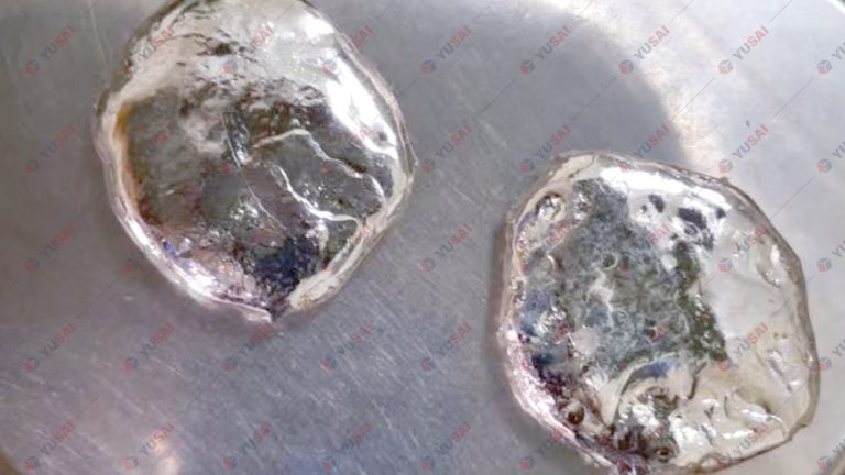

If you be interested in our equipment and solutions, please to contact us.
- +86 18339216321
- info@yusaipreciousmetals.com
- zhengzhou.henan.china