
Copper Electrolytic Cell

— Copper Electrolytic Cell: Cell Body, Electrode Pitch and Current Distribution Engineering
A copper electrolytic cell is the vessel in which cast blister-copper anodes are dissolved and the same copper is redeposited on stainless steel cathode blanks as 99.99% cathode copper, with a homopolar electrode pitch of about 100 mm between plate centres, a cathode current density of 300 A/m² at the design point inside the 200–350 A/m² commercial band, and a cell voltage of 0.25–0.35 V per cell at the terminals. YuSai Machinery engineers the cell itself — its body construction and internal geometry, working volume, electrode pitch and array, busbar and equipotential intercell connection, insulating scheme against stray current, electrolyte inlet and thermal loop, cell covers and mist extraction, and the tooling that turns the cell over between campaigns — from your own anode assay and target cathode tonnage, so that the cell holds its current distribution and its cathode grade for the whole anode cycle.
Product Overview
A copper electrolytic cell is the vessel in which copper electrorefining actually happens: cast blister-copper anodes and stainless steel cathode blanks hang alternately in a copper sulphate and sulphuric acid electrolyte, a direct current is passed through the cell, and the copper leaves the anode, crosses the liquor and returns to the solid state on the cathode at 99.99% purity. Everything else in a copper refinery — the anode furnace and casting wheel that produce the plates, the rectifier and switchgear, the circulation and thermal loop, the electrolyte purification circuit, the cathode stripping and washing machine, the slime treatment plant — exists to feed this vessel, hold it in its operating window and take its products away. This page is about the cell at that level: the geometry and the materials that set its current distribution, the electrical furniture that carries the current, and the numbers that tell you what it will produce.
The electrochemistry inside the cell is simple to state and demanding to control. At the anode, metallic copper loses two electrons and enters the electrolyte as the cupric ion, Cu − 2e⁻ = Cu²⁺. At the cathode, the cupric ion gains the same two electrons and returns to the metallic state, Cu²⁺ + 2e⁻ = Cu. Because the reversible potential of the two reactions is the same, the decomposition voltage of a copper cell is very small and almost the whole of the cell voltage is polarisation and resistance rather than thermodynamics. That single fact is what makes the cell an electrical engineering problem as much as a chemical one. Everything that does not dissolve either sinks or stays: gold, silver, the platinum group metals and part of the selenium and tellurium are nobler than copper, do not enter the electrolyte and settle to the cell floor as anode slime, while nickel, iron, arsenic, antimony and bismuth dissolve alongside the copper and accumulate in the liquor, where they are managed by the electrolyte purification circuit rather than by the cell. The cell therefore does two jobs at once — it transports copper from an impure plate to a pure plate, and it sorts every other element into exactly one of two streams.
Current density is the parameter that decides both the output and the quality of the cathode, and it is the number a copper cell specification most often leaves undefined. This cell is designed around a cathode current density of 300 A/m² inside the 200–350 A/m² band that commercial refineries occupy, with headroom towards 400 A/m² where the anode chemistry and the clean-up capacity allow it. Raising the current density is paid for in three currencies: the resistive drop across the inter-electrode path, which rises with current and with the electrode gap; the approach to the limiting current density at the cathode face, where cupric ions can no longer be supplied to the surface fast enough and roughness, nodulation and dendritic growth begin; and the impurity balance, because a faster campaign gives the impurities less time to be bled out. Mass transfer is therefore part of the cell rather than an accessory of it: the homopolar pitch sets the ohmic path, the inlet and overflow arrangement sweep the plate faces, the temperature holds the conductivity up, and the glue, thiourea and chloride balance holds the deposit level and fine-grained.
The electrical arrangement of a copper cellhouse is what makes the cell geometry consequential. The electrodes inside one cell are connected in parallel, so the cell current is the sum of the currents drawn by its cathodes and the cathode count multiplied by the cathode area and the current density gives the cell current directly. The cells themselves are connected in series, so the current is common to the whole cellhouse while the cell voltages add along the string, which is why a copper refinery rectifier is specified for a modest voltage and a very large current. Within the cell, each anode stands between two cathodes, which means there is always one more anode bus than cathode bus, and the current path runs from an anode bus through the liquor to the cathodes either side of it and on to the next anode. Contact resistance at the hanger and at the busbar joint is one of the few terms in that path that changes during a campaign, which is why it is measured at commissioning and monitored afterwards.
The geometry of the cell is where the two objectives meet and sometimes conflict. A tighter pitch shortens the ohmic path and lowers the cell voltage and the energy per tonne, but it also reduces the margin against deposit bridging, circulation starvation and a bowed plate touching through. A longer cell carries more electrodes and therefore more current for the same rectifier voltage, but it needs a longer busbar run and a flatter floor, and it concentrates more slime into one floor area. A deeper cell holds more copper as working inventory and gives more freeboard for foam and mist, but it raises the hydrostatic load on the walls and the pumping duty. There is no universal answer to any of these: the pitch, the electrode count and the working volume are set from the anode envelope, the anode chemistry, the campaign length and the floor available, and they are issued as design outputs with the drawings rather than left to be discovered during commissioning.
The liabilities of a copper cell are specific and the design contains them rather than describing them. Sulphuric acid mist is generated where oxygen bubbles burst at the electrolyte surface, so the cells are covered individually and the headspace is drawn from under the cover at a small directed air volume. Slime that detaches from an anode and floats rather than settles can plate onto a cathode and put arsenic, antimony or bismuth into the product, which is why the slime is kept at the cell floor by the floor slope and the flow pattern and why the slime box is drained on schedule rather than at convenience. Nodules and dendrites that grow across the gap short-circuit a cathode and waste the current that was meant to plate it, which is why per-cell voltage and per-cathode current are both monitored and why the response to an anomaly is to find the component that changed rather than to raise the current. And the stray-current path through the cell furniture, the support beams and the floor is designed out at the outset, because a cellhouse that leaks current into its own structure is expensive and slow to put right afterwards.
Because anode composition, impurity profile, anode envelope, target tonnage and available floor area vary widely between one project and the next, the cell is sized from your own numbers rather than from a table of standard tanks. The cathode area is calculated from the copper equivalent of the current, the target daily cathode output, the current efficiency and the design current density; the electrode count and the cell length follow from the cathode area and the pitch; the working volume and the copper held as working inventory follow from the cathode area and the campaign length; and the cell current, busbar section, rectifier rating, circulation rate, cooling duty and extraction volume are then fixed around them. Working as a copper electrolytic cell manufacturer from the anode backwards, we state those figures in the process design package, and we would rather revise the anode specification or the cell geometry than supply a cell that cannot hold its cathode grade.
Key Facts
- Cell body constructions offered: polymer concrete cast from silica sand and vinyl ester resin with FRP seal layers, reinforced concrete with an acid-resistant resin lining, FRP, and polypropylene for smaller and laboratory duties.
- Cell geometry basis: internal length follows from the electrode count multiplied by the homopolar pitch, and the working volume follows from the cathode area and the campaign length, so the tank is dimensioned from the duty rather than selected from a table of standard tanks.
- Electrode pitch: 100 mm centre-to-centre is the standard homopolar distance offered with the 316L stainless cathode platform, and the working band is about 95–110 mm. A 100 mm pitch leaves roughly 30 mm of free electrolyte between facing electrode surfaces, and that path is the dominant resistive term in the cell voltage.
- Electrodes per cell: commercial copper cells carry about 30 to 60 anode–cathode pairs. The electrodes inside one cell are electrically in parallel while the cells themselves are connected in series, so the cell current is the sum of the cathode currents and the cellhouse voltage is the sum of the cell voltages.
- Anode and cathode: cast blister-copper anodes of roughly 1 m by 1 m and 40–50 mm thick at about 300–400 kg, alternating with 316L stainless steel cathode blanks of about 3.25 mm blade thickness carrying polypropylene edge strips, each presenting about 2 m² of deposition surface and stripping at 120–150 kg.
- Cathode current density: 300 A/m² at the design point inside the 200–350 A/m² band that commercial copper refineries occupy, with headroom towards 400 A/m² where the anode chemistry and the electrolyte clean-up allow it.
- Electrochemical equivalent of copper: 1.186 g of copper per ampere-hour from the Cu²⁺/Cu couple at 100% current efficiency, which is 0.02846 kg per ampere-day. A cell’s daily output is the cell current multiplied by 1.186 g per ampere-hour, by the hours under load and by the current efficiency.
- Cell voltage and energy: 0.25–0.35 V per cell at the design current density, with a practical minimum of about 0.15 V. At 0.30 V and 95% current efficiency the rectifier energy is about 266 kWh per tonne of cathode copper, which is the arithmetic behind the 250–300 kWh per tonne that copper refineries report.
- Busbar arrangement: one more anode bus than cathode bus in every cell, because each anode stands between two cathodes and the end anodes close the array, with equipotential intercell bars carrying the current from one cell to the next.
- Electrolyte window: 40–50 g/L copper, 160–200 g/L free sulphuric acid, 20–50 mg/L chloride and 60–65 °C, with glue and thiourea as the organic levelling and grain-refining agents and chloride dosed as their surface-active partner.
- Anode slime: generated at 0.2–1.0% of anode mass and collected in the slime box formed into the sloped cell floor, carrying the gold, silver, platinum group metals, selenium and tellurium that do not dissolve anodically.
- Two streams that decide the economics: current efficiency, held at 92–97% by current distribution and contact discipline, and the slime, which is where the by-product credit of a copper cellhouse is realised.
- Configuration: cell count, cell dimensions, working volume, electrode pitch, cell current, busbar section, rectifier rating, circulation rate, cooling duty, extraction volume and effluent duty are engineered to your anode assay, target cathode tonnage and site conditions rather than taken from a catalogue of fixed models.
Product Core Selling Points
- The cell is dimensioned from the duty, not selected from a stock tank. Internal length follows from the electrode count multiplied by the homopolar pitch, width and depth follow from the anode envelope and the freeboard the liquor needs, and the working volume follows from the cathode area and the campaign length. Because every dimension traces back to a number you supplied, the cell can be audited on paper against its own specification before it is built.
- Cathode area and cell current are arithmetic, not judgement. Copper carries 1.186 g per ampere-hour. A cathode presenting 2 m² of deposition surface at 300 A/m² draws 600 A; thirty such cathodes make a cell of about 18 kA delivering roughly 487 kg of copper a day at 95% current efficiency; and the cell count for a target tonnage is that figure divided into the daily requirement. The whole chain is stated in the process design package.
- A 100 mm homopolar pitch is a specified dimension, not a tolerance. The pitch is set with spacing elements and checked with a gauge across the whole array, because the free electrolyte path between facing plate surfaces fixes the ohmic term of the cell voltage and limits how much deposit can grow before it bridges to the anode.
- The insulating scheme is designed against stray current. Cells stand on insulated beams and the busbar is insulated from the cell furniture, so current is kept inside the electrode array instead of finding a parallel path through concrete, steelwork and the floor. Stray current is difficult to correct after commissioning and free to eliminate in design.
- Equipotential intercell bars instead of bolted cell-to-cell joints. The bars that carry current between adjacent cells are equipotential, which removes the bolted joint between cells as a resistance term, lowers the total cellhouse voltage at a given current, and gives the short-circuit detection system a clean signal to work from.
- One more anode bus than cathode bus, deliberately. Every anode stands between two cathodes so that both faces of every cathode plate work, and the end anodes close the array and carry the current into the next cell. Getting this arrangement right is what makes the current density uniform along the strip instead of concentrated on the end plates.
- Cell voltage issued as a component budget. The voltage is quoted per cell at the terminals and split into electrode terms, the electrolyte ohmic term across the inter-electrode path, and the contact and conductor terms. A voltage that moves during a campaign is worked through the components in a fixed order, which turns it into a diagnosis rather than a puzzle.
- Energy per tonne stated as a checkable figure. At 0.30 V and 95% current efficiency the rectifier energy is about 266 kWh per tonne of cathode copper. That single figure is the fastest way to test whether a quoted cell voltage, current density and efficiency set is internally consistent.
- Copper cell bodies built for sulphuric acid service. Polymer concrete cast from silica sand and vinyl ester resin with FRP seal layers, reinforced concrete with a resin lining, FRP, or polypropylene, selected against the liquor and the site rather than against first cost, with a sloped floor and a slime box formed into the base.
- Slime is treated as a product stream, not as cleaning. The sloped floor carries slime into a defined collection box, the box is drained and the slime is washed, dewatered, weighed and assayed so that every lot leaves the plant declared by metal content.
- Cell covers and extractive ventilation as part of the cell. Individual cell covers hold the acid mist generated at the electrolyte surface and the extraction is taken from under the cover at a small directed air volume, so the scrubber and fan are sized for the mist actually produced rather than for the volume of the building.
- Turnover tooling included in the cell scope. Lifting beams, electrode handling gear, spacing gauges, contact dressing tools and the cathode stripping interface are supplied with the cell, so the campaign changeover is a procedure rather than an improvisation.
- Cell duty engineered to your assay. Cell count, dimensions, working volume, electrode pitch, busbar section, rectifier rating, circulation rate, cooling duty and extraction volume are stated in the process design package against your anode assay, target cathode tonnage, product form and site conditions.
Application Scenarios
- Copper smelters converting blister copper to cathode copper. An anode furnace and a casting wheel produce the plates, and the cellhouse is the step that turns them into a saleable LME Grade A cathode rather than a discounted impure anode.
- Refineries where the anode slime is the economic driver. Operations whose margin comes from the gold, silver, platinum group metals, selenium and tellurium in the slime, and where the cell therefore has to be designed for slime recovery and declaration rather than for cathode tonnage alone.
- Secondary copper and e-waste smelters. Copper recovered from printed circuit boards, cable, motors and mixed electronic scrap, smelted and cast into anodes that carry an unpredictable impurity load and need a cell that can be worked batch by batch.
- Hydrometallurgical plants producing impure copper. Cement copper, black copper and electrowon powder from solvent extraction that has to be consolidated, cast and electrorefined before it can be sold as cathode.
- Tankhouses converting from starter sheets to permanent cathodes. Operations still producing and handling copper starter sheets, where the same cell volume is asked to carry more current with less labour and a more consistent cathode.
- Cellhouses expanding inside an existing footprint. Plants that cannot add a second row of tanks and need more cathode tonnage from the floor area they already have, which is a question of electrode pitch and current density as much as of cell count.
- Operations where cathode grade fails on antimony and bismuth. Houses fighting floating slime and co-deposited impurities, where the fix is at the cell — flow pattern, floor slope, slime removal and a tighter pitch — as much as in the purification circuit.
- Plants where cell voltage and energy per tonne have to come down. Operations with a rising energy bill per tonne of cathode, where the audit runs through contact resistance, busbar joints, electrode pitch and electrolyte temperature in that order.
- Copper scrap and alloy processors. Brass, bronze, copper alloy and mixed copper scrap melted and cast into anodes where the alloying elements are the impurity load the cell has to separate.
- Plating, PCB and metal-finishing operations recovering copper. Copper from spent plating baths, etching solutions, drag-out and rinse water, concentrated and cast into anodes so the metal can be returned to the line or sold as cathode.
- Copper rod and wire mills wanting in-house cathode. Downstream producers who would rather control their own cathode assay and traceability than buy on the spot market.
- Toll and contract refineries. Third-party anodes refined in campaigns, where the cell has to be reconfigured between feeds and every lot closes on a weighed balance and a certificate of analysis.
- Small and modular refineries. Reduced-capacity cellhouses built as modules from a single cell upward, where the same sizing arithmetic scales down rather than being replaced by a different concept.
- Mints, assay offices and metallurgical laboratories. Small-volume, well-characterised work where the requirement is a documented purity and a controlled current distribution rather than throughput.
Applicable Raw Materials
The cell accepts metallic copper feed, and every feed below enters the cell through the anode. Material that is already metallic and castable is melted under flux and cast into plates on a casting wheel or into a mould set sized to the anode envelope the cell accepts; material that arrives as cement, powder, shot or residue is dried, fluxed and consolidated into a cast anode rather than fed loose; and material carrying an impurity profile that would poison the electrolyte is blended or pre-treated before the anode is cast. Output is stated for each feed.
- Blister copper anodes from a converter. The classic feed, 98–99.5% copper, cast into plates with formed lugs and dressed faces, and the grade the cell geometry is normally proved against. Output: 99.99% cathode copper and a precious-metal-bearing anode slime.
- Fire-refined copper anodes above 99.2% copper. Plates from an anode furnace that have already been oxidised and poled, carrying only the residual impurity load, and the feed that gives the longest electrolyte life between bleeds. Output: 99.99% cathode copper with a low-yield slime.
- Re-melted copper scrap cast into anodes. Cable, tube, busbar and offcut copper melted under flux and cast to the anode envelope, with the flux and blowing conditions set from the assay. Output: 99.99% cathode copper and a base-metal slag returned for copper recovery.
- Cement copper and black copper consolidated into anodes. Precipitated or partially reduced copper consolidated by drying, fluxing and melting, which removes a handling problem and produces a feed the cell can actually dissolve. Output: cathode copper and a declared slime fraction.
- Copper powder and electrowon copper from solvent extraction. Fine or dendritic copper that will not survive in a plate, briquetted or melted into an anode before it reaches the cell. Output: cathode copper from feed that would otherwise have to be sold as powder.
- Electronic scrap derived copper anodes. Copper from printed circuit boards, connectors, cable and mixed electronic scrap, smelted and cast, carrying appreciable gold, silver, palladium and nickel and therefore needing a slime route and a bleed schedule sized for it. Output: cathode copper and a precious-metal slime declared by metal content.
- Copper alloy and brass anodes. Copper with zinc, tin, lead or nickel in the matrix, cast into anodes once the alloying elements have been assessed against the electrolyte balance. Output: cathode copper and a base-metal stream to the purification circuit.
- Residual anode plates from a previous campaign. Partly dissolved plates that have reached the end of their dissolution cycle, returned to the melting shop and cast into fresh anodes rather than written off as scrap. Output: remelted anode plates returned to the cell.
- Anode scrap, croppings and lug offcuts. The trimmed material generated by anode preparation, remelted and returned so that the copper circulates internally instead of leaving the plant at a discount. Output: anode copper recovered into the next cast.
- Copper bearing sludges and filter cakes. Copper hydroxide, carbonate and cement filter cakes dried, fluxed and consolidated before casting, with the liquor from the filtration routed to the water balance rather than discharged. Output: cast anode feed and a base-metal filtrate.
- Copper from spent plating and etching solutions. Electrolytic or chemical copper recovered from plating baths, etchant and drag-out, concentrated and cast into anodes so that the metal returns to the plating line as cathode rather than leaving as a regulated waste. Output: cathode copper returned to the line or sold.
- Anodes with an elevated nickel content. Feed where nickel builds up in the liquor rather than reporting to the slime, raising the copper sulphate solubility limit and the anode passivation risk, so the bleed and the nickel recovery route are sized from the assay. Output: cathode copper and a nickel-bearing electrolyte bleed to recovery.
- Anodes with an elevated arsenic, antimony and bismuth content. Feed that makes the arsenic balance against antimony and bismuth the governing constraint on cathode quality, and that sets the slime handling regime from the first campaign. Output: cathode copper held to specification and a slime fraction routed to arsenic control.
- High-selenium and high-tellurium anodes. Feed where the selenium and tellurium report to the slime and are recovered as by-products, so the slime route is designed with that recovery in mind rather than as a waste stream. Output: cathode copper and a selenium and tellurium fraction separated from the slime.
Finished Products
The cell is configured around the product form the customer sells and the stage at which the customer takes delivery. Where the customer already operates an anode furnace, a casting wheel, a stripping machine and an assay laboratory, the cellhouse is delivered with the cell, the busbar, the circulation and thermal loop and the instrumentation only; where it does not, anode preparation, cathode handling, slime collection and product finishing are included with it.
- Cu-CATH-1 cathode copper at 99.99%. The primary product of the cell: refined copper deposited on both faces of each cathode blank, stripped, washed free of entrained electrolyte, dried and bundled to a declared weight. Output: cathode bundles at 99.99% copper with a certificate of analysis.
- LME Grade A cathode. Copper refined to a specification that allows the bundle to be accepted at a rod mill or delivered against a futures contract without being re-melted. Output: brand-registered cathode accepted on warrant.
- Cut, chopped and sampled cathode. Cathode sheared to a size the customer’s melting or sampling routine requires, with the sampling tooling chosen so that it does not import iron into the sample. Output: cathode cut to length with a lot sample.
- Copper rod, bar and billet. Where continuous casting or a rod mill sits downstream, the cathode is melted and cast into the semi-finished form sold to the wire and cable industry. Output: copper rod or billet from in-house cathode.
- Anode slime declared by metal content. The most valuable by-product of the cell, generated at 0.2–1.0% of anode mass and carrying the gold, silver, platinum group metals, selenium and tellurium that did not dissolve; washed free of entrained electrolyte, dewatered, dried, weighed and assayed. Output: assayed slime concentrate with every metal declared before it leaves the plant.
- Precious metal fraction from the slime. Where the feed carried appreciable gold, silver or platinum group metals, the slime is further treated or declared as a separate fraction so that the value is priced rather than carried as a bulk concentrate. Output: gold, silver and PGM bearing fraction with declared metal content.
- Selenium and tellurium by-products. Where the anode carried these elements, they report to the slime and are separated as their own product stream rather than being left in a residue. Output: selenium and tellurium fraction to the by-product circuit.
- Nickel sulphate or nickel carbonate from the bleed. Nickel dissolved at the anode is removed from the electrolyte as a crystallised or precipitated salt, turning an impurity that would otherwise have to be disposed of into a saleable by-product. Output: nickel salt of declared grade.
- Copper recovered from the liberator or scavenger circuit. Copper removed from the electrolyte bleed and from the lean liquor before the impurities are taken out, returned to the anode melt or sold as high-grade recovered copper. Output: recovered copper returned to the anode furnace.
- Recast anode plates from residual anode stock. Partly dissolved plates returned to the melting shop and cast into fresh anodes rather than written off, so the copper circulates inside the plant. Output: remelted anode plates returned to the cell.
- Regenerated electrolyte. Electrolyte from which the accumulated copper, nickel, arsenic, antimony and bismuth have been removed and the acid balance restored, returned to the cellhouse rather than being sent to effluent. Output: electrolyte returned to service at the working specification.
- Cathode wash water returned to the circuit. The water used to rinse entrained electrolyte from the stripped cathodes carries copper that belongs back in the process, so it is collected and returned rather than sewered. Output: wash water returned to the water balance.
- Scrubbed exhaust and treated effluent. Cell headspace mist captured under the covers and scrubbed, and process effluent neutralised, metal-polished and either recirculated or discharged at the agreed limits. Output: emission and effluent records filed with the batch.
- Batch documentation. Every lot is released with the anode weight and assay, the electrolyte analysis at make-up and at draw-off, the cell campaign record including ampere-hours and current efficiency, the slime weight and assay, the cathode assay and the metal balance for that lot. Output: certificate of analysis and batch record.
Copper Electrolytic Cell Process Flow
The nine stages below are the working cycle of one copper electrolytic cell, from the duty it has to carry through to its clean-out and return to service. It is written at cell level rather than at plant level on purpose: this is the sequence a cell designer, a tankhouse foreman and a metallurgist work through when the question is how a cell is dimensioned, how its current distribution is set up and what has to be done to it between campaigns. Cell count, cell dimensions, working volume, electrode pitch, cell current, busbar section, rectifier rating, circulation rate, cooling duty and extraction volume are fixed during process design against your own anode assay, target cathode tonnage and site.

Copper electrolytic cell working cycle — from the duty review that fixes the geometry through the deposition stage to the wash-down and return to service, with the electrolyte, the cathode copper and the anode slime kept inside the circuit.
Steps 1 — Cellhouse Duty Review and Cell Sizing Arithmetic. The cell is dimensioned before any concrete is poured, and the arithmetic runs in one direction only. Copper carries 1.186 g per ampere-hour, so a cell required to produce 487 kg of copper a day has to average 20.3 kg an hour; at a current efficiency of 95% that is 18.0 kA of cell current; and at a design cathode current density of 300 A/m² over 2 m² of deposition surface per cathode it is 30 cathodes in the cell. The cell current, the cathode count and the current density then fix the remaining dimensions: the electrode pitch sets the internal length, the anode envelope sets the width and depth, the working volume follows from the cathode area and the campaign length, and the busbar section, rectifier rating, circulation rate, cooling duty and extraction volume are all derived from the same sheet. The anode assay is the input that governs everything downstream, because the impurity load it reports is what sets the bleed schedule and the achievable current density. Reagent and utility input: anode assay and impurity suite, target daily cathode tonnage, anode envelope and weight, site drawings and available floor area, current efficiency basis. Output: cell count, cell dimensions, working volume, electrode pitch and cathode count, cell current, and the busbar, rectifier, circulation, cooling and extraction duties that follow.
Steps 2 — Cell Body Casting, Resin Lining and Tightness Test. The cell body is produced in the material the liquor and the site call for: polymer concrete cast from silica sand and vinyl ester resin with an FRP seal layer, reinforced concrete with an acid-resistant resin lining, FRP, or polypropylene for a smaller duty. The wall thickness, the ribbing and the base support are set by the hydrostatic load of the working volume plus the freeboard the liquor needs, and the sloped floor and the slime box are formed into the base at the same time rather than added later, because the floor slope is what decides whether slime travels to the slime box or settles where it lands. The cell is hydrostatically tested before it is set, the lining is inspected for holidays and pinholes, and the outlets are checked in the positions the flow pattern requires. Reagent and utility input: polymer concrete with vinyl ester resin, FRP seal layers, acid-resistant resin lining or polypropylene, mould set, slime box and floor slope formwork, hydrostatic test rig. Output: an acid-tight cell body with a sloped floor and a formed slime box, dimensionally within the drawing tolerance.
Steps 3 — Cell Setting on Insulated Beams and Level Survey. The cell is set on support beams that are insulated from the structure, so that the cell body, the beams and the floor do not become an alternative path for the current and so that a leak cannot put the tankhouse structure at the potential of the circuit. Level is what matters next: the cell is surveyed along its length and across its width, because the liquor surface is the datum from which electrode immersion depth is measured and a cell that is out of level will run a different current through each end of the array. The setting is checked with the cell empty and again with the working volume in it, since the loaded deflection of a long cell is a real quantity and the electrode immersion depth is set from the loaded level rather than the empty one. Reagent and utility input: insulated support beams and insulating pads, survey and levelling equipment, shims and grout, containment bunding and segregated drainage connection. Output: a level, electrically isolated cell on surveyed beams with its containment and drainage connected.
Steps 4 — Electrode Pitch Setting and Plate Interleaving. The electrode array is set out on the homopolar pitch the design calls for, 100 mm centre-to-centre in the standard configuration and inside a working band of about 95–110 mm. The pitch is held by spacing elements and the cell furniture and is verified with a gauge across the whole array, because at a 100 mm pitch only about 30 mm of free electrolyte separates two facing plate surfaces and that dimension is the dominant resistive term in the cell voltage. Anodes and cathodes are interleaved so that every anode stands between two cathodes and both faces of every cathode plate work, and the array is closed by an anode at each end, which is why there is one more anode bus than cathode bus. Every plate is checked for straightness, because a bowed plate changes the gap along its own length and produces a current distribution that follows the bow rather than the design. Reagent and utility input: spacing elements and cell furniture, anode and cathode support rails, pitch gauge and setting jig, plate straightness check, immersion depth gauge. Output: a squared electrode array at the design pitch with the immersion depth recorded and every plate free to be lifted.
Steps 5 — Anode Loading, Lug Seating and Cathode Dressing. The anode is the feed and the electrode at the same time, so how it is loaded decides both how evenly it dissolves and how evenly the cell distributes current. Each cast anode of 300–400 kg is checked for flatness and thickness, its lugs are trimmed so that both contact faces sit flat on the busbar, and the plate is weighed so that the current it will carry is known. The cathode blank is 316L stainless steel of about 3.25 mm blade thickness; the blank is inspected for straightness and surface condition, degreased where it is new or has been reconditioned, fitted with polypropylene edge strips that keep the deposit off the plate edges, and mounted on its hanger bar. The electrodes are then lowered into the cell on a lifting beam to the design pitch and every hanger is seated on its bus. Contact is the part of the job that is hardest to correct later: a resistive contact does not stop the current, it routes it around the cathode it was meant to build. Reagent and utility input: cast blister-copper anodes, 316L stainless steel cathode blanks with edge strips and hanger bars, anode lug trimming and straightening gear, degreasing agents, lifting beam and electrode handling gear, weighing and thickness gauges. Output: weighed anodes and dressed cathode assemblies seated on the bus at the design pitch, with lug and hanger contacts clean and flat.
Steps 6 — Busbar and Equipotential Intercell Bar Installation. The busbars are installed on insulated supports with the conductor section the cell current requires, and the joints and hanger clamps are dressed and torqued rather than tightened by feel. The intercell connection uses equipotential bars instead of a bolted joint between adjacent cells, which removes the cell-to-cell joint as a resistance term, lowers the total cellhouse voltage at a given current, and gives the short-circuit detection system a cleaner signal because the voltage measured across a cell is no longer polluted by the joint at each end of it. Insulation between the busbar and the cell furniture is checked point by point, and the polarity of the series string is verified at the terminals before any current is applied. Reagent and utility input: busbar conductor with dressed contact faces, equipotential intercell bars, hanger clamps and bolted joints at specified torque, insulating pads and barriers between bar and furniture, contact resistance meter, polarity check. Output: a completed current path from the rectifier through the cell and on to the next cell, with insulation verified and contact resistances recorded as the commissioning baseline.
Steps 7 — Per-Cathode Current Balancing on the Start-Up Ramp. Current is brought up on a staged ramp rather than switched to its full value, because the first hours decide the character of the deposit: a modest starting current produces a coherent fine-grained seed layer that later growth can build on, whereas a cold start at full current produces a burst of nodules and a deposit that later sheds back into the electrolyte. Individual cathode currents are measured as the current steps up, so that a poor contact, a mis-set plate or a bowed blank is found on the first day rather than at harvest, and the split between cathodes is adjusted before the cell reaches its design current. Busbar and joint temperatures are confirmed stable at each step, and the ampere-hour count for the campaign starts when the cell is at full load. Reagent and utility input: rectifier with staged current programme, per-cathode current measurement, busbar and joint temperature instrumentation, insulation verification, ramp record sheet. Output: a uniform current split across the cathode set, a coherent seed deposit established, and the corrected settings recorded against the campaign.
Steps 8 — Voltage Audit and Thermal Scan Over the Array. Once the cell is at its design current it is monitored through three quantities: per-cell voltage, per-cathode current and joint temperature. A cell voltage that rises at constant current is worked through in a fixed order — contact faces first, then electrode pitch and immersion depth, then electrolyte temperature and composition, and only then the current programme — because raising the current to recover the deposition rate would raise the voltage further and take the cathode grade with it. Thermal scanning of hangers, clamps and joints finds the resistive contact before it becomes a hot joint. Nodule and dendrite growth that bridges the gap between a cathode and its anode shows up as a deviation in the cathode current split, and the response is to lift the affected cathode on the scheduled cycle rather than to let it short the cell for the rest of the campaign. Reagent and utility input: per-cell voltage monitoring, per-cathode current measurement, infrared thermal scanning of contacts and joints, nodule inspection and cathode lifting gear, cell record sheet. Output: a cell held at 92–97% current efficiency with faults localised to a component and recorded against the campaign.
Steps 9 — Cathode Harvest, Slime Box Recovery and Cell Wash-Down. When the deposit has taken up its design load, judged from the ampere-hours passed against the plate weight and confirmed by weighing the drained cathode, the cell is taken out of service and the cathode set is lifted on the crane and the lifting beam. The cathode is stripped, and the stripped copper is washed to remove adhering electrolyte and copper sulphate, which is a specification step rather than housekeeping, because residual sulphate on the plate surface is a rejection point and the wash water carries copper that belongs back in the circuit rather than down the drain. The slime box is drained and the slime is recovered, washed free of entrained electrolyte, dewatered, weighed and assayed so that the lot is declared by metal content. The cell floor, the covers and the extraction duct connection are washed on the same schedule so that material which settled out of the circuit is recovered rather than hosed away, the cell is inspected, and the array is re-dressed at the design pitch with fresh plates before the cell is returned to service. Reagent and utility input: overhead crane and lifting beam, cathode stripping and washing equipment, slime box draining and slime washing, dewatering and drying, slime weighing and assay, cell wash-down with collected liquor, pitch gauge and re-dress tools. Output: bundled 99.99% cathode copper at the certified assay; washed, dried and assayed anode slime declared by metal content; wash water and recovered residues returned to the circuit; a cleaned and inspected cell returned to service.
Product Structure (Main Equipment)
The cell is assembled from the three equipment groups below, all of them cell-level rather than plant-level. Materials are selected stream by stream: polymer concrete cast from silica sand and vinyl ester resin with FRP seal layers, reinforced concrete with an acid-resistant resin lining, FRP or polypropylene for the body; 316L stainless steel for the cathode blade with polypropylene edge strips; copper or copper-clad conductor for the busbar with insulated supports at every point where it passes the cell furniture; and PP, PVDF and FRP for wetted parts, piping and ducting.
Cell body, lining and process containment
- Polymer concrete cell body. A cell cast from silica sand bound with vinyl ester resin and sealed with FRP layers, which resists sulphuric acid at working temperature, holds its dimensions under a full working volume, and can be cast with the floor slope and the slime box formed in. Output: an acid-tight, dimensionally stable cell body that does not depend on a lining for its integrity.
- Reinforced concrete cell with resin lining. Where the site prefers a concrete structure, the cell is built in reinforced concrete and lined with an acid-resistant resin or sheet lining, with the lining inspected for holidays before the cell is charged. Output: a heavy-duty cell at a lower capital cost, with the lining as the barrier that is inspected and renewed.
- FRP and polypropylene cells. Filament-wound FRP and moulded polypropylene bodies for duties where a lighter or more chemically specific construction suits the liquor, the building or the size of the cell. Output: a cell matched to the liquor and the site rather than to a single house standard.
- Sloped floor and slime box. A floor formed on a slope towards a defined collection box, so that slime which falls from the anodes travels to one place instead of settling where it lands, and the box is drained and recovered on schedule rather than at convenience. Output: a slime stream that can be recovered and declared instead of a floor that has to be shovelled.
- Individual cell covers. A cover over each cell rather than a hood over the aisle, holding the sulphuric acid mist that the oxygen bubbles generate at the liquor surface and giving the extraction a small, well-directed air volume to treat. Output: captured acid mist at the point of generation and an exhaust volume the scrubber can be sized for.
- Insulated support beams and containment. Support beams with insulating pads between the beam and the cell and between the beam and the structure, a containment bund under the cell and a segregated floor drainage path that runs to the effluent plant rather than to the storm system. Output: no stray-current path through the structure, and a spill or a leak held inside the process boundary.
Electrode array, cell furniture and current delivery
- Cast copper anodes with formed lugs. Anode plates cast to the envelope the cell accepts, with lugs formed and trimmed so that both contact faces sit flat on the bus, and with the cast weight and thickness recorded against the lot. Output: weighed anodes with a known dissolution area and a verified contact face.
- 316L stainless steel cathode blanks. Permanent cathode blanks of about 3.25 mm blade thickness, chosen because they release the deposited copper cleanly on stripping, tolerate the acid electrolyte, and can be reused for many campaigns instead of being melted with the product. Output: a cathode surface that strips cleanly and is returned straight to the cell.
- Polypropylene edge strips and corner protection. Insulating edge strips that keep the deposit off the plate edges, so that the stripped copper separates without tearing and the blank is not damaged at the edge where the current density is highest. Output: clean stripping and a longer blank life.
- Hanger bars and contact faces. Hanger bars with dressed contact faces that carry the cathode current onto the bus and are checked for resistance rather than for tightness, because a resistive hanger contact is the most common single cause of a lost current efficiency. Output: a low-resistance, repeatable contact path from blank to busbar.
- Cell furniture and pitch setting elements. Support rails, stops, spacer elements and setting jigs that fix the homopolar pitch and hold the electrode array square, with the spacing verified by gauge across the whole array rather than trusted to the furniture. Output: a uniform inter-electrode pitch along the full immersed length.
- Anode and cathode busbars. Anode and cathode busbars sized on the cell current and the permissible current density in the conductor, supported on insulation, with the arrangement giving one more anode bus than cathode bus because every anode stands between two cathodes. Output: current delivered to every electrode at a conductor temperature the design allows.
- Equipotential intercell bars. Bars that carry the current from one cell to the next at equal potential, removing the bolted cell-to-cell joint as a resistance term, lowering the cellhouse voltage at a given current and cleaning up the voltage signal the monitoring system works from. Output: a lower total cellhouse voltage and a cleaner cell voltage measurement.
- Insulation and stray-current barriers. Insulation between the busbar and the cell furniture, between the beams and the structure, and at every point where a conductor passes near a structural member, so that no member of the building becomes a parallel current path. Output: current confined to the electrode array, with no stray-current corrosion of the structure.
Electrolyte feed, thermal loop and cell instrumentation
- Inlet distributor and overflow arrangement. Electrolyte is introduced low in the cell and withdrawn at the opposite end over an overflow, so that the flow sweeps the plate faces rather than short-circuiting across the top of the array, and the withdrawal is arranged so that slime that has settled is not drawn back into the circulation. Output: a flow pattern that holds the copper concentration uniform at the cathode face and keeps the slime at the floor.
- Circulation pump and header. A corrosion-resistant circulation pump and a distribution header feeding each cell, with the flow rate set per cell from the cathode area and the current density rather than from the pump curve. Output: a controlled and repeatable flow rate at every cell in the house.
- Heat exchanger and thermal control set. A heat exchanger with a control loop holding the electrolyte in the 60–65 °C band, either heated from waste heat or steam and cooled as the process requires, with the measurement taken in liquor the electrodes actually stand in. Output: electrolyte held at the temperature the conductivity and the additive balance assume.
- Electrolyte filtration and additive dosing. Filtration ahead of the cells to remove suspended solids that would otherwise report to the cathode, and metered dosing of glue, thiourea and chloride matched to the current and the electrolyte condition. Output: a clean feed liquor and a controlled additive balance, held on the analysis rather than on the operator’s judgement.
- Level, temperature and flow instrumentation. Level indication on the cell, temperature measurement at the cell and flow indication on the feed, so the state of the cell is read from its own instruments rather than inferred from the pump or the header. Output: a cell whose operating window can be verified at the cell.
- Cell voltage, per-cathode current and joint temperature monitoring. Per-cell voltage logging, per-cathode current measurement and thermal scanning of hangers, clamps and joints, which together are the whole diagnostic set for current distribution and short circuits. Output: a cell that reports its own current distribution and localises a fault to a component.
- Cathode lifting beam and turnaround tooling. The lifting beam, electrode handling gear, spacing gauges, contact dressing tools and stripping machine interface that turn a campaign changeover into a procedure rather than an improvisation. Output: a repeatable turnaround with the electrode pitch re-set to the drawing at every re-dress.
- PLC control and cell record. PLC control covering rectifier start and stop, current and voltage setting, circulation and thermal sequences and alarm annunciation, with an event log that records the campaign against the lot number along with the ampere-hours and the current efficiency. Output: repeatable campaigns and a process record that stands behind the batch documentation.
Product Features
- Cell dimensions derived from the duty rather than taken from a stock tank. Internal length follows from the electrode count multiplied by the homopolar pitch, width and depth from the anode envelope and the freeboard, and the working volume from the cathode area and the campaign length, so every dimension of the cell traces back to a number supplied by the customer.
- Cathode area and cell current calculated, not estimated. The cathode area comes from the copper equivalent of the current, the target daily output, the current efficiency and the design current density; the cell current is then the cathode count multiplied by the cathode area and the current density, which is a figure that can be checked on paper before the cell is built.
- A 100 mm homopolar pitch held by furniture and verified by gauge. The spacing elements set the pitch and the gauge confirms it across the whole array, because at that pitch only about 30 mm of free electrolyte separates two facing plate surfaces and that path is the ohmic term of the cell voltage.
- One more anode bus than cathode bus, by design. Each anode stands between two cathodes so that both faces of every cathode plate work, the end anodes close the array, and the current path runs anode to cathode to anode along the cell rather than along a single plate.
- Electrodes in parallel within the cell, cells in series across the house. The electrical arrangement is stated rather than implied, because the cell current is the sum of the cathode currents while the cellhouse voltage is the sum of the cell voltages — which is why the rectifier is specified for a large current and a modest voltage.
- Equipotential intercell bars instead of bolted cell-to-cell joints. Removing the joint between cells takes a resistance term out of the cellhouse voltage and gives the monitoring system a cell voltage that reflects the cell rather than the connection at each end of it.
- An insulating scheme that stops stray current at the source. Cells on insulated beams, busbar insulated from the cell furniture, and insulating barriers wherever a conductor passes near a structural member, so no part of the building becomes a parallel current path.
- Cell voltage issued as a component budget. The voltage is quoted per cell at the terminals and split into electrode terms, the electrolyte ohmic term across the inter-electrode path, and the contact and conductor terms, so a change during a campaign can be assigned to a component and corrected rather than compensated with more volts.
- Energy per tonne as a checkable number. At 0.30 V and 95% current efficiency the rectifier consumes about 266 kWh per tonne of cathode copper, which gives any quoted voltage, current density and efficiency set a consistency test that does not depend on the supplier’s own figures.
- Polymer concrete, lined concrete, FRP and polypropylene cell bodies. The body is selected against the liquor, the site and the size of the cell, with the floor slope and the slime box cast into the base rather than fitted afterwards.
- Slime collected, not shovelled. The sloped floor carries slime to a formed collection box, the box is drained on schedule, and the slime is washed, dewatered, weighed and assayed so that every lot leaves the plant declared by metal content.
- Cell covers and extractive ventilation inside the cell scope. The acid mist generated at the liquor surface is captured under an individual cover at a small directed air volume, so the scrubber and the fan are sized for the mist the cells actually produce rather than for the volume of the building.
- Current distribution instrumented at three levels. Per-cell voltage, per-cathode current and hanger and joint temperature, which together identify a short circuit, a resistive contact or a mis-set plate before the affected cathode is lost.
- Turnover tooling supplied with the cell. Lifting beam, electrode handling gear, spacing gauges, contact dressing tools and the stripping machine interface, so that the campaign changeover is a documented procedure and the pitch is re-set to the drawing at every re-dress.
- Cell duty engineered to your assay. Cell count, dimensions, working volume, electrode pitch, busbar section, rectifier rating, circulation rate, cooling duty and extraction volume are all stated in the process design package against your anode assay, target cathode tonnage, product form and site conditions.
Technical Parameters And Specifications
Copper electrolytic cell technical parameters. Cell dimensions, working volume and electrode count are engineered to your anode envelope, anode assay and target cathode tonnage; the figures below are the design values the cell is specified against.
| Parameter | Specification |
|---|---|
| Primary function | Electrolytic refining of copper in a cell, dissolving a cast blister-copper anode in a copper sulphate and sulphuric acid electrolyte and depositing 99.99% cathode copper on a stainless steel cathode blank, with the gold, silver, platinum group metals, selenium and tellurium retained in the anode slime |
| Cell duty basis | Cathode area and cell current calculated from the copper equivalent of the current, the target daily cathode output, the current efficiency and the design current density; cell count then follows from the cell current against the target tonnage |
| Cell body construction — polymer concrete | Cast from silica sand bound with vinyl ester resin and sealed with FRP layers; resists sulphuric acid at working temperature and holds its dimensions under a full working volume |
| Cell body construction — lined concrete | Reinforced concrete with an acid-resistant resin or sheet lining, inspected for holidays before charging; used where the site prefers a concrete structure |
| Cell body construction — FRP and polypropylene | Filament-wound FRP or moulded polypropylene bodies for duties where a lighter or more chemically specific construction suits the liquor, building or cell size |
| Cell internal geometry | Internal length equals the electrode count multiplied by the homopolar pitch; width and depth follow from the anode envelope plus the freeboard the liquor and the mist need; all dimensions stated in the process design package |
| Cell working volume | Sized from the cathode area and the campaign length, and stated together with the copper held as working inventory in solution rather than as a tank dimension alone |
| Cell floor and slime collection | Sloped floor formed in the base and draining to a defined slime box, so slime travels to one place instead of settling where it lands; the box is drained and recovered on schedule |
| Cell support and insulation | Cells set on insulated support beams with insulating pads between beam, cell and structure; containment bunding under the cell with a segregated floor drainage path to the effluent plant |
| Cell covers and mist extraction | Individual cover per cell holding the sulphuric acid mist generated at the liquor surface, with extraction taken from under the cover at a small directed air volume and ducted to the scrubber |
| Anode form | Cast blister-copper plate with formed lugs, cast weight and thickness recorded against the lot; roughly 1 m by 1 m and 40–50 mm thick in the standard envelope |
| Anode weight | About 300–400 kg per plate in the standard envelope, and set from the anode envelope the cell accepts and the handling equipment available |
| Anode preparation | Lugs milled and trimmed so both contact faces sit flat on the bus, plate straightened and checked for flatness and thickness, surface inspected for shrinkage voids and casting defects |
| Anode dissolution cycle | About 21–28 days depending on anode thickness and current density, with 12–20% of the original weight remaining as residual plate returned to the melting shop |
| Cathode form | 316L stainless steel permanent cathode blank, flat and inspected for surface condition, degreased when new or reconditioned and reusable for many campaigns |
| Cathode blade thickness | About 3.25 mm as the standard platform, with the blank thickness and stiffness set by the deposit load and the stripping equipment |
| Cathode edge strips | Polypropylene insulating edge strips keeping the deposit off the plate edges, so the copper strips cleanly and the blank is protected where current density is highest |
| Cathode deposition surface | About 2 m² per cathode counted on both faces of the immersed blade, which is the area basis the cathode current density is quoted against |
| Loaded cathode weight | About 120–150 kg per cathode at the design current density and the design stripping cycle |
| Homopolar electrode pitch | 100 mm centre-to-centre as the standard, inside a working band of about 95–110 mm, held by the cell furniture and verified with a gauge across the whole array |
| Free electrolyte path between plate faces | About 30 mm at the standard pitch and blade thickness, and the dominant resistive term in the cell voltage at a given current density |
| Electrodes per cell | About 30 to 60 anode–cathode pairs, set from the cathode area and the pitch; the array is closed by an anode at each end and the electrodes are checked for freedom to be lifted |
| Cell electrical arrangement | Electrodes within a cell connected in parallel; cells connected in series across the cellhouse, so the cell current is the sum of the cathode currents and the cellhouse voltage is the sum of the cell voltages |
| Busbar arrangement | One more anode bus than cathode bus, because every anode stands between two cathodes; anode and cathode busbars sized on the cell current and the permissible conductor current density |
| Busbar conductor and contacts | Conductor section sized on the cell current, with dressed and torqued contact faces at every hanger and joint, and contact resistance measured and recorded as the commissioning baseline |
| Equipotential intercell bars | Bars carrying the current from one cell to the next at equal potential, removing the bolted cell-to-cell joint as a resistance term and giving a cleaner cell voltage measurement |
| Cathode current density | 300 A/m² at the design point, inside the 200–350 A/m² band that commercial copper refineries occupy, with headroom towards 400 A/m² where the anode chemistry and the clean-up capacity allow it |
| Electrochemical equivalent of copper | 1.186 g of copper per ampere-hour from the Cu²⁺/Cu couple at 100% current efficiency, equivalent to 0.02846 kg per ampere-day |
| Daily copper output basis | Cell current multiplied by 1.186 g per ampere-hour, by the hours under load and by the current efficiency, reduced by the efficiency actually achieved on the material |
| Cell voltage | 0.25–0.35 V per cell at the terminals at the design current density and inside the working temperature band, with the pitch and the temperature the figure assumes stated alongside it |
| Minimum practical cell voltage | About 0.15 V, below which the electrode reactions and the liquor cannot be held at the design conditions |
| Cell voltage components | Stated separately as four terms: the anode dissolution term, the cathode deposition term, the electrolyte ohmic term (current density multiplied by the inter-electrode path divided by the liquor conductivity) and the contact and conductor term |
| Current efficiency | 92–97% in normal operation, held by current distribution, contact discipline, electrode pitch and the additive balance rather than by the rectifier setpoint |
| Energy consumption per tonne | About 266 kWh per tonne of cathode copper at 0.30 V and 95% current efficiency, against the 250–300 kWh per tonne reported by operating copper refineries |
| Rectifier and control | Rectifier rated on the cellhouse current and the string voltage, in constant-current or constant-voltage mode as the flowsheet specifies, at the local voltage and frequency, with staged ramp capability for start-up |
| Electrolyte system | Copper sulphate in sulphuric acid, with glue and thiourea as the levelling and grain-refining agents and chloride as their surface-active partner |
| Copper concentration in electrolyte | 40–50 g/L as Cu²⁺, held in band because a low copper tenor raises the mass transfer limit and the roughness risk at high current density |
| Free sulphuric acid | 160–200 g/L, which carries the conductivity of the liquor and suppresses base metal co-deposition, balanced against its effect on anode passivation |
| Chloride | 20–50 mg/L dosed as hydrochloric acid or a chloride salt, acting with thiourea to form the surface-active complex that improves levelling; excess chloride attacks the stainless steel blanks and is held inside specification |
| Organic additives | Glue and thiourea dosed continuously rather than in batches, because batch dosing produces concentration swings that show up as deposit quality variation across the strip |
| Electrolyte temperature | 60–65 °C set point, which balances conductivity, copper solubility and additive stability; higher temperatures accelerate glue degradation and thiourea decomposition |
| Electrolyte circulation | Flow introduced low in the cell and withdrawn at the opposite end, at a rate set per cell from the cathode area and the current density, so the copper concentration at the cathode face stays close to the bulk value |
| Electrolyte filtration | Filtration ahead of the cells to remove suspended solids that would otherwise report to the cathode as inclusion, with the filter duty set from the slime behaviour of the anode |
| Anode slime yield | 0.2–1.0% of anode mass, collected in the slime box formed into the sloped cell floor |
| Anode slime handling | Slime drained from the box, washed free of entrained electrolyte, dewatered, dried, weighed and assayed, with every lot declared by metal content before it leaves the plant |
| Cathode cycle | About 6–14 days depending on the current density and the deposit load, with the cycle set so that no cathode is allowed to grow past the deposit quality it can hold |
| Cell instrumentation | Per-cell voltage logging, per-cathode current measurement, joint and hanger thermal scanning, cell level measurement, electrolyte temperature at the cell and flow indication on the feed |
| Short-circuit and hot-contact detection | Cathode current deviation identifies a short circuit, thermal scanning identifies a resistive contact, and per-cell voltage identifies a cell whose distribution has changed, all read against the commissioning baseline |
| Materials of construction — wetted parts | Polymer concrete with vinyl ester resin and FRP seal layers, acid-resistant resin lining, FRP, polypropylene, 316L stainless steel, PP and PVDF for piping, pump internals and filter media |
| Product purity | 99.99% copper at the cathode, from an anode cast from blister copper of 98% copper and above; cathode accepted to Cu-CATH-1 and to LME Grade A specification |
| Verification | Cathode assay and anode and slime assays by the customer’s or the brand’s specification, with each lot released against a certificate of analysis and a closed metal balance |
| Capacity, cell count, power, footprint and utilities | Engineered to your anode assay, target cathode tonnage, product form and site conditions |
| Installation | Indoor, on a surveyed and level floor, with insulated support beams, containment and the segregated drainage arrangements shown on the layout drawing |
Technical Advantages
- Throughput comes from the cathode area and the current density, not from cell volume. A cell’s daily copper output is its current multiplied by 1.186 g per ampere-hour and by the hours under load, so the way to more copper is more cathode area at a defensible current density rather than a larger tank. The cathode count, the pitch and the cell current are the three numbers that carry the tonnage, and all three are stated in the design package.
- The sizing arithmetic can be audited before the cell is built. Copper at 1.186 g per ampere-hour, a cathode at 2 m², a design density of 300 A/m² and a current efficiency of 95% give a chain that anyone can follow: 600 A per cathode, 18 kA for a thirty-cathode cell, about 487 kg a day, and a cell count for the target tonnage. A cell specified this way cannot quietly under-deliver.
- Energy per tonne is defended by geometry, not by the rectifier. Cell voltage is dominated by the ohmic term across the inter-electrode path, so the homopolar pitch, the plate flatness and the electrolyte temperature are the levers on power. Holding 0.30 V rather than 0.35 V is worth roughly 44 kWh per tonne of cathode copper at the same current efficiency.
- Contact resistance is managed as a measured quantity. The single most common cause of a lost current efficiency in a copper cellhouse is a resistive contact that does not stop the current but routes it away from the cathode it was meant to build. Contact faces are dressed and torqued to specification, resistance is measured at commissioning and recorded as a baseline, and joints are scanned thermally in service.
- Equipotential intercell bars take a resistance term out of the cellhouse. Carrying the current between cells at equal potential removes the bolted cell-to-cell joint, which lowers the total voltage at a given current and gives the monitoring system a cell voltage that reflects the cell rather than the connections at each end of it.
- Stray current is designed out rather than tracked down. Cells on insulated beams, busbar insulated from the cell furniture, and insulating barriers wherever a conductor passes a structural member. A cellhouse that leaks current into its own structure corrodes it and is expensive to correct after commissioning.
- The mass transfer limit is addressed instead of discovered. Concentration polarisation caps cathode current density before the rectifier does, so the inlet and overflow arrangement, the pitch and the temperature are treated as cell geometry rather than as accessories, and the cell is designed against the limiting current density at its own copper tenor rather than against a nominal figure.
- Cathode grade is defended at the cell as well as in the purification circuit. Antimony and bismuth damage cathode quality by adhering to the deposit as floating slime, so the floor slope, the flow pattern, the slime box and the bleed schedule are set together, and the slime is removed on schedule rather than at convenience.
- Current distribution is instrumented at three levels, so faults are localised rather than guessed. Per-cell voltage, per-cathode current and joint temperature distinguish a short circuit, a resistive contact and a mis-set plate, and every one of them is compared against the commissioning baseline rather than against a nominal figure.
- Slime is recovered as a product rather than cleaned up as a nuisance. The floor slope and the slime box deliver a single recoverable stream, the slime is washed, dewatered, weighed and assayed, and each lot is declared by metal content, which is where a copper cellhouse earns its by-product credit.
- The additive balance is held on continuous dosing and analysis. Glue, thiourea and chloride are dosed continuously against the current and the electrolyte analysis, because batch dosing swings the concentration and the swing is visible in the deposit.
- Cell construction is matched to the liquor and the site. Polymer concrete, lined concrete, FRP and polypropylene are offered on their own merits, with the sloped floor and the slime box formed into the base, so the cell is not forced into a material that suits the supplier’s mould rather than the duty.
- Configuration stated in writing before manufacture. Cell count, dimensions, working volume, electrode pitch, cell current, busbar section, rectifier rating, circulation rate, cooling duty, extraction volume and effluent duty are engineered from your anode assay and target cathode tonnage and issued as a process design package rather than discovered at commissioning.
Service Process
Step 1 — Feed Characterisation and Cell Consultation. Send a representative sample or a typical analysis of your blister copper, fire-refined copper, cement copper, scrap-derived anode or copper-bearing residue, with the anode envelope you can cast, the batch or continuous pattern and the daily cathode tonnage you intend to produce. Our metallurgical team assays it for copper and for the impurity suite that governs the cell design — nickel, arsenic, antimony, bismuth, lead, iron, selenium, tellurium and chloride — together with the precious metal content that sets the slime credit. Output: assay report and a preliminary cell proposal with the achievable cathode grade, the current density the anode chemistry supports and the expected slime yield.
Step 2 — Laboratory Test Work and Cell Design. Bench and pilot campaigns confirm the anode composition and casting conditions, the electrolyte specification and the additive balance, the current density the anode and the mass transfer limit allow, the expected cathode morphology, the slime yield and composition, and the bleed and purification schedule. The results are converted into the cell body construction and internal geometry, the cathode area and electrode count, the homopolar pitch, the working volume and the copper held as inventory, the busbar section and insulating scheme, the rectifier rating, the circulation and cooling duty, the extraction volume, a layout and a utility schedule against your tonnage and site. Output: test report, cell design package with the voltage and energy budgets and firm quotation.
Step 3 — Cell Fabrication and Module Assembly. The cell body is cast or built to drawing with the floor slope and the slime box formed in and the lining applied where the construction requires it; the cell furniture, pitch setting elements and support beams are fabricated; the busbars are produced and the insulating scheme is assembled; and the inlet distributor, overflow, covers, extraction connection and instrumentation are fitted and piped. Output: an assembled, pre-piped and pre-insulated cell module.
Step 4 — Factory Assembly, Testing and Acceptance. Each cell is checked for acid tightness and dimensional tolerance, the electrode array is trial-fitted and the homopolar pitch verified with a gauge, the insulation resistance of the busbar and support scheme is measured, and the cell is functionally tested with the customer invited to attend the factory acceptance test. The contact resistance of every hanger, clamp and joint is measured and recorded as the baseline that the commissioning figures will be compared against. Output: a FAT-approved cell with its inspection, dimensional and contact resistance records.
Step 5 — Shipping, Installation and Commissioning. We supervise the civil interface, the survey and levelling of the cell support, erection, the setting of the busbar and insulation, piping, ducting and the electrical tie-in, then run an instrumented commissioning campaign on your anodes until the contracted cathode grade, current density and current efficiency are demonstrated and the extraction and effluent streams are verified against your local limits. Output: a producing copper electrolytic cell at contracted performance with its commissioning record.
Step 6 — Operator Training and Handover. On-site training covers anode handling and lug seating, cathode blank dressing and edge strip replacement, electrode pitch setting and verification, cell loading and immersion depth control, electrolyte make-up, sampling and titration, additive dosing, current density and temperature control, reading per-cell voltage and per-cathode current, thermal scanning and contact dressing, cathode stripping and washing, slime box recovery and slime handling, mist extraction and effluent operation, emergency procedures and assay quality control, supported by standard operating procedures and a full handover dossier. Output: a trained crew and complete documentation.
Step 7 — Process Optimisation and Ongoing Support. Remote troubleshooting, reagent and consumable supply, cathode blank, edge strip and contact hardware service, periodic performance audits in which the cathode assay, the electrolyte analysis, the slime yield and the energy per tonne are reviewed against the design, and cell or capacity upgrade paths keep the cellhouse at target over its service life. Output: sustained performance and spare-part continuity.
Warranty And After-Sales Service
- Warranty period. Twelve months from commissioning or eighteen months from shipment, whichever falls first, covering design, materials and workmanship of the equipment supplied, with the terms and the excluded wear parts stated in the contract.
- Wear part and consumable clarity. Contact hardware, edge strips, pump seals, filter media, gaskets and linings are identified as consumables with their expected service intervals declared up front, so the operating cost of the cell is visible before it is commissioned rather than after.
- Cathode blank service. Inspection, straightening and repair of the stainless steel blanks and replacement of edge strips and hanger bars, so the surface the copper is deposited on is maintained rather than run until the deposit quality falls.
- Spare parts availability. A recommended commissioning and first-year spares set is quoted with the cell, and spare parts remain available through the equipment’s service life with lead times stated at order.
- Remote support. Telephone, email and messaging support for operating questions, alarm interpretation, current distribution faults, cell voltage deviations, cathode quality problems and process troubleshooting while your cellhouse is running. Output: same-day response on operating issues.
- On-site service. Engineer attendance for warranty faults, process problems and periodical check-ups, with response and attendance times agreed in the contract according to your location. Output: on-site intervention and a service report.
- Cell relining and overhaul support. Assistance with lining inspection and renewal, cell body repair, insulation verification, busbar and contact refurbishment and the re-setting of the electrode pitch, so that a mid-life overhaul is planned rather than reactive. Output: a documented overhaul with the cell returned to drawing tolerance.
- Assay and metal balance verification service. Periodic verification of the cathode assay, the electrolyte analysis and the slime weight and assay against your own laboratory results, so the performance of the cell is tracked over time rather than assumed from commissioning. Output: verification report against the campaign records.
- Operator retraining and refresher visits. Additional training, refresher sessions and process optimisation visits as your anode source, impurity profile or product requirement changes. Output: updated training and revised procedures.
- Documentation set. Operation and maintenance manuals, cell drawings and electrode arrangement, busbar and insulation drawings, electrical and control drawings, layout, spare parts catalogue, safety data for sulphuric acid and the reagents used, and the emergency response plan covering acid exposure, electrical isolation and a cell spill. Output: complete documentation handover.
- Compliance support. Assistance with emission and effluent parameter declarations, acid mist extraction and scrubbing performance verification, and the handling, storage and disposal requirements for acid-bearing process liquors, slime and the intermediates generated at the cell. Output: technical data for your permit applications.
- Lifetime technical support. The cell design and its sizing arithmetic remain yours, and our engineering team remains available for modification and expansion advice for the operating life of the cellhouse. Output: long-term engineering continuity.
Frequently Asked Questions
What is a copper electrolytic cell?
A copper electrolytic cell is the vessel in which cast blister-copper anodes and stainless steel cathode blanks hang alternately in a copper sulphate and sulphuric acid electrolyte and a direct current moves the copper from the impure plate to the pure one. At the anode the metal dissolves as the cupric ion, Cu – 2e- = Cu2+, and at the cathode the same ion gains the electrons back and returns as solid metal, Cu2+ + 2e- = Cu. Because both electrodes are copper, the reversible potentials cancel and almost the whole of the cell voltage is polarisation and resistance rather than thermodynamics, which is why the cell is as much an electrical problem as a chemical one. The cell contains the electrodes, the electrolyte, the busbars that carry the current to every plate, the circulation and thermal loop, the covers that capture the acid mist, and the sloped floor and slime box that recover the anode slime. It is the unit in which the process numbers are actually fixed: cathode area and current density set the daily output of cathode copper, cell voltage multiplied by cell current sets the power, and the working volume sets the copper held as working inventory.
How does a copper electrolytic cell differ from a copper electrowinning cell?
By what is fed to it. An electrolytic cell, or electrorefining cell, takes metallic feed — a cast blister-copper anode that dissolves anodically and leaves behind an anode slime carrying the gold, silver, platinum group metals, selenium and tellurium that did not dissolve. An electrowinning cell takes a solution — a leach liquor, a strip liquor or a bleed stream — through an inert anode that does not dissolve, so there is no anode slime, the anode reaction is oxygen evolution rather than metal dissolution, and the cell voltage is around 1.9 to 2.1 V rather than 0.3 V because the decomposition voltage of the water reaction has to be supplied. In copper practice the two are complementary rather than alternative: electrowinning recovers the copper left in the lean liquor and in the electrolyte bleed, while electrorefining is what turns a cast anode into a saleable LME Grade A cathode. This page describes the refining cell.
How is the geometry of a copper electrolytic cell fixed?
From the cathode area and the electrode pitch. The cathode area comes from the copper equivalent of the current, which is 1.186 g of copper per ampere-hour, the target daily output, the current efficiency and the design current density; the electrode count then follows from the cathode area and the area per cathode, the internal length follows from the electrode count multiplied by the homopolar pitch, the width and depth follow from the anode envelope plus the freeboard the liquor and the mist require, and the working volume follows from the cathode area and the campaign length. A cell required to make 487 kg of copper a day has to average 20.3 kg an hour, which at 95% current efficiency is 18.0 kA of cell current, and at 300 A/m² over 2 m² of deposition surface per cathode that is 30 cathodes on a 100 mm pitch, which puts the internal length at a little over three metres of working electrode array. Every one of those figures is issued in the process design package rather than discovered at commissioning.
What is the electrode pitch in a copper electrolytic cell, and why does it matter?
The pitch is the centre-to-centre distance between neighbouring electrodes, and 100 mm is the standard homopolar distance offered with the permanent cathode platform, inside a working band of about 95 to 110 mm. It matters twice over. Electrically, the pitch sets the length of the electrolyte path the current has to cross: at a 100 mm pitch with a 40 to 50 mm anode and a 3.25 mm blade, only about 30 mm of free liquor separates two facing plate surfaces, and that short path is what keeps the ohmic term of the cell voltage — and therefore the energy per tonne — small. Practically, the pitch also sets how much deposit can grow before it bridges to the anode and short-circuits the cell. A tighter pitch lowers the voltage but removes margin, so the pitch is held by the cell furniture, verified with a gauge across the whole array, and re-set at every re-dress rather than left to the tolerance of the plates.
What cell voltage does a copper electrolytic cell run at?
0.25 to 0.35 V per cell at the terminals at the design current density and inside the working temperature band, with about 0.15 V as the practical floor below which the design conditions cannot be held. The figure is low compared with most electrochemical cells because both electrodes are copper and the reversible potentials cancel, leaving polarisation and resistance as the whole of the voltage. It is worth knowing why quoted figures differ between suppliers: one may be quoting the potential across a single electrode pair, another the voltage measured at the cell terminals including the contacts at both electrode sets, and a third the rectifier output across a string of series-connected cells, which includes the conductor drop between cells. Spacing and current density then move the ohmic term and temperature moves the conductivity it depends on. This cell is quoted per cell at the terminals with the pitch and the temperature the figure assumes stated alongside it.
How is the cell voltage budget accounted for component by component?
As four separate terms. The anode term is the polarisation required to dissolve copper from the plate and to manage the slime blanket that forms on it; the cathode term is the polarisation required to reduce the cupric ion at the cathode face, which rises as the copper concentration at the surface falls away from the bulk value; the ohmic term is the current density multiplied by the free electrolyte path between the plate faces and divided by the conductivity of the liquor; and the contact term is the resistance at the hanger faces, the clamps and the busbar joints at both electrode sets, plus the conductor drop along the bus. The first two are electrochemical and are what they are; the last two are engineering, and they are the two a properly built cell keeps small. Issuing the budget as four figures is what turns a voltage change during a campaign into a diagnosis: the component that moved tells you whether to look at contacts, geometry, temperature or the anode face.
How much energy does copper electrorefining consume per tonne of cathode?
About 266 kWh per tonne of cathode copper at 0.30 V and 95% current efficiency, and between 250 and 300 kWh per tonne across the range of cell voltages and efficiencies that operating copper refineries report. The figure is easy to check from first principles. One tonne of copper at 1.186 g per ampere-hour requires about 843,000 ampere-hours; multiplying that charge by 0.30 V and dividing by the current efficiency gives the kilowatt-hours. Because almost all of that voltage is the ohmic term across the inter-electrode path, the levers on energy per tonne are geometric rather than electrical: the pitch, the plate flatness, the contact condition and the electrolyte temperature. Holding 0.30 V rather than 0.35 V is worth roughly 44 kWh per tonne at the same current efficiency, which is the reason a cell voltage budget is issued as a component breakdown rather than as a single number.
How much copper does one electrolytic cell produce per day?
It depends on the cell current, and the cell current depends on how many cathodes the cell carries and at what current density. The calculation is the cell current multiplied by 1.186 g per ampere-hour, by the number of hours under load and by the current efficiency. Take a cell of 30 cathodes, each presenting 2 m² of deposition surface at a design density of 300 A/m², so each cathode draws 600 A and the cell carries about 18 kA. Over 24 hours at 95% current efficiency that is about 487 kg of copper, and across a cellhouse of 60 such cells it is roughly 29 tonnes a day, or the order of 10,600 tonnes a year on continuous operation with the cathode cycle included. The cathode area, not the tank volume, is what sets the tonnage, so the cell is sized from the target output rather than from a standard tank.
What is the cell body made of, and which construction should be chosen?
Four constructions are in normal use and the choice follows from the liquor, the site and the size of the cell. Polymer concrete cast from silica sand bound with vinyl ester resin and sealed with FRP layers is the most common modern solution: it resists sulphuric acid at working temperature, holds its dimensions under a full working volume, and can be cast with the floor slope and the slime box formed into the base. Reinforced concrete with an acid-resistant resin or sheet lining is used where the site prefers a structural concrete cell, with the lining as the barrier that is inspected and renewed and the concrete as the load-bearing member. Filament-wound FRP suits duties where a lighter body is wanted, and moulded polypropylene suits smaller and laboratory cells. In every case the deciding points are the same: acid tightness at the working temperature, dimensional stability under the hydrostatic load, an electrically insulating body so that the cell does not become a current path, and a floor that can be sloped so the slime can be recovered.
Why do copper electrolytic cells stand on insulated beams?
Because the cellhouse is a series electrical circuit and the cell bodies, the support beams and the building structure are all conductors of a sort. If a cell is earthed through its support, or if a beam becomes a parallel path, part of the cellhouse current flows through the structure instead of through the electrodes, which is the definition of stray current. The consequences are corrosion of the structure and the reinforcement, unreliable cell voltage readings, and a current efficiency that is lower than the metal balance predicts. The remedy is designed in rather than tracked down afterwards: cells set on support beams with insulating pads between the beam and the cell and between the beam and the structure, busbar insulated from the cell furniture at every point where it passes near a structural member, and the insulation resistance measured at commissioning and re-verified at every major overhaul.
Why is there one more anode bus than cathode bus in a copper cell?
Because of how the electrodes are interleaved. Anodes and cathodes alternate, and every anode stands between two cathodes so that both faces of every cathode plate are doing work rather than one. The array is closed by an anode at each end, which means that for fifty-nine cathodes there are sixty anodes, and therefore one more anode bus than cathode bus. The arrangement is not a detail: it is what makes the current density uniform along the active face of the cathode instead of concentrating at the edges, and it means the current path in the cell runs anode to cathode to anode along the row rather than along a single plate. It is also why the end anodes of a cell have to be loaded first and lifted last, and why an uneven anode count is one of the first things to check when a cell shows a cathode-to-cathode current spread that cannot be explained by contacts.
What is an equipotential intercell bar, and why does it matter?
It is the connection that carries the current from one cell to the next at equal potential, instead of a bolted joint through which the whole cellhouse current passes between adjacent cells. With an equipotential bar the anodes of one cell and the cathodes of the next are effectively at the same potential along the bar, so the current transfers without the resistance of a bolted joint at each end of every cell. Three things follow. The cellhouse voltage at a given current is lower, because a resistance term has been removed rather than reduced. The cell voltage measured at a cell reflects the cell rather than the two connections at its ends, which is what makes per-cell voltage a usable diagnostic for current distribution and short circuits. And the joint that would otherwise be a maintenance item and a hot spot under load is largely eliminated, so the thermal survey concentrates on the electrode contacts where the real variability lives.
How is a short circuit or a hot contact found in a copper electrolytic cell?
By three measurements working together, all read against the baseline recorded at commissioning. Per-cell voltage tells you that something in that cell has changed, but not what, because a single shorted cathode inside a cell of thirty barely moves the cell voltage. Per-cathode current measurement is what localises it: a shorted or bridged cathode draws less current than its neighbours while the rest of the cell absorbs the difference, so the deviation identifies the electrode to lift. Thermal scanning of hangers, clamps and busbar joints identifies the resistive contact, which shows as a hot joint at a fraction of the current it should be carrying, and it is done as a routine rather than after a fault because a resistive contact does not stop the current, it routes it away from the cathode it was meant to build. Together the three distinguish a short circuit, a hot contact and a mis-set or bowed plate without stopping the cell.
What electrolyte composition and temperature does a copper electrolytic cell hold?
Copper at 40 to 50 g/L as the cupric ion, free sulphuric acid at 160 to 200 g/L, chloride at 20 to 50 mg/L, and 60 to 65 °C, with glue and thiourea as the organic levelling and grain-refining agents. Each bound has a reason. The copper tenor sets the margin against the mass transfer limit at the cathode face, and running it low raises the roughness risk at high current density. The acid carries the conductivity of the liquor and suppresses base metal co-deposition, but it also raises the risk of anode passivation, so it is held inside a window rather than pushed up. Chloride is dosed deliberately as the partner of thiourea in the surface-active complex that improves levelling, and is held inside specification because excess chloride attacks the stainless steel blanks. Temperature balances conductivity, copper solubility and additive stability: higher temperatures conduct better but degrade glue and thiourea faster and drive evaporation and mist losses up.
Why is chloride dosed into the electrolyte of a copper cell?
Because it is not an impurity in this process, it is a reagent. At concentrations between about 20 and 50 mg/L, dosed as hydrochloric acid or a chloride salt, the chloride ion interacts with thiourea to form a surface-active complex that improves the levelling performance of the organic additive system, which is what holds the deposit smooth and fine-grained at commercial current densities. The upper bound is a materials limit rather than a process one: chloride attacks stainless steel, and the 316L cathode blanks and the stainless components of the cellhouse are what set the ceiling. That is why the chloride figure is specified as a band with a dosing system and an analysis routine behind it rather than as a maximum, and why the risk of chloride rising is managed by holding the additive balance and the bleed together rather than by dosing less chloride and accepting a rougher deposit.
What is the anode slime yield, and where does it collect in the cell?
Slime is generated at 0.2 to 1.0% of the anode mass, so the yield follows from the anode weight and the number of anodes dissolved rather than from the cell. It is the fraction of the anode that does not dissolve anodically — gold, silver, the platinum group metals, part of the selenium and tellurium, and insoluble compounds of lead and of antimony and bismuth — and it is where a copper cellhouse earns its by-product credit. In the cell it collects in two places and the design keeps it out of a third. Most of it falls from the anode face and is carried by the sloped floor to a formed collection box at the low end, which is drained on a schedule rather than at convenience. Some remains on the anode and is carried out with the residual plate and removed at the re-dress. The third place is the cathode, and the design work is to keep it out of there: slime that floats rather than settles can adhere to the deposit and carry antimony and bismuth into the cathode assay, which is why the floor slope, the flow pattern and the drain schedule are treated as quality controls rather than housekeeping.
What is verified before a copper electrolytic cell is accepted?
Six things, and they are verified twice. In the factory the cell body is checked for acid tightness and for dimensional tolerance against the drawing; the electrode array is trial-fitted and the homopolar pitch verified with a gauge across the whole array; the insulation resistance of the busbar, the hanger supports and the beam pads is measured; and the contact resistance of every hanger, clamp and joint is measured and recorded as the commissioning baseline, because that baseline is what every later reading is compared against. On site the cell support is surveyed and the cell levelled with the working volume in it, the electrode immersion depth is confirmed, and an instrumented commissioning campaign runs on your own anodes until the contracted cathode grade, current density and current efficiency are demonstrated and the extraction and effluent streams are verified against the local limits. The acceptance package carries the inspection record, the dimensional record, the insulation and contact resistance records and the commissioning report, and every subsequent lot is released against a certificate of analysis with a closed metal balance. The method of measurement for each of those items is agreed in the contract before manufacture, so acceptance does not depend on how the figures are produced.
Main related equipment and processes: precious metal recovery equipment, precious metal extraction equipment, precious metal recovery & extraction system, non-ferrous metal extraction equipment, precious metal refining equipment, precious metal purification equipment, precious metal refining & purification system, precious metal recovery & refining system, precious metal hydrometallurgical refining plant, platinum group metal refining equipment, platinum palladium rhodium refining equipment, platinum palladium rhodium purification equipment, platinum palladium rhodium recovery & refining plant, gold refining machine, silver refining machine, gold refining process, silver refining process, platinum refining process, palladium refining process, rhodium refining process, ruthenium refining process, precious metal electrolysis equipment, precious metal electrowinning equipment, gold electrolysis equipment, silver electrolysis equipment, copper electrolysis equipment, gold electrowinning equipment, silver electrowinning equipment, copper electrowinning equipment, gold electrolysis machine, silver electrolysis machine, gold electrolytic cell, silver electrolytic cell, copper electrolytic cell, etc.

Get A Free Quote
Fill in the form below and our service team will get back to you within 24 hours with a recommended process flow and quotation.
- +86 18339216321
- info@yusaipreciousmetals.com
- Zhengzhou.Henan.China
- Precious Metal Recovery Equipment
- Precious Metal Extraction Equipment
- Precious Metal Recovery & Extraction System
- Non-Ferrous Metal Extraction Equipment
- Precious Metal Refining Equipment
- Precious Metal Purification Equipment
- Precious Metal Refining & Purification System
- Precious Metal Recovery & Refining System
- Precious Metal Hydrometallurgical Refining Plant
- Platinum Group Metal Refining Equipment
- Platinum Palladium Rhodium Refining Equipment
- Platinum Palladium Rhodium Purification Equipment
- Platinum Palladium Rhodium Recovery & Refining Plant
- Gold Refining Machine
- Silver Refining Machine
- Gold Refining Process
- Silver Refining Process
- Platinum Refining Process
- Palladium Refining Process
- Rhodium Refining Process
- Ruthenium Refining Process
- Precious Metal Electrolysis Equipment
- Precious Metal Electrowinning Equipment
- Gold Electrolysis Equipment
- Silver Electrolysis Equipment
- Copper Electrolysis Equipment
- Gold Electrowinning Equipment
- Silver Electrowinning Equipment
- Copper Electrowinning Equipment
- Gold Electrolysis Machine
- Silver Electrolysis Machine
- Gold Electrolytic Cell
- Silver Electrolytic Cell
- Copper Electrolytic Cell
- Precious Metal Smelting Machine
- Precious Metal Granulator
- Gold & Silver Ingot Casting Mold
- Vacuum Ingot Casting Machine
- Lead Refining Machine
- Lead Smelting Furnace
- Lead Refining Furnace
- Lead Refining Plant
- Oxygen-Enriched Bottom-Blown Furnace
- Oxygen-Enriched Side-Blown Furnace
- Smelting Furnace
- High Frequency Smelting Furnace
- Medium Frequency Smelting Furnace
- Split Tilting Smelting Furnace
- Lead-Copper Anode Slime Converter
- 1600℃ Induction Heating Furnace
- 1600℃ Medium Frequency Melting Furnace
- Atomization Powder Making Equipment
- Electromagnetic Induction High Frequency Heating Furnace
- NOx Treatment Equipment
- Acid & Alkaline Gas Treatment Equipment
- Flue Gas Absorption Tower
- Laboratory Waste Gas Treatment Equipment
- Enamel Reactor
- Neutralization Reactor
- Pickling Agitation Tank
- Horizontal Continuous Casting Machine
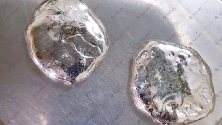

If you be interested in our equipment and solutions, please to contact us.
- +86 18339216321
- info@yusaipreciousmetals.com
- zhengzhou.henan.china